Copyright 2015, Rapidlogger Systems
www.rapidlogger.com
The Rapidlogger RapidDCC system is used to control the automatic mixing of oilfield cement slurries without the operator having to constantly adjust the water and bulk feed rates. The Rapidlogger RapidDCC system accomplishes this by controlling the water flow valve and the bulk feed gate valve. It constantly monitors the mixing density and adjusts the two valves appropriately. The system also monitors the tank level by means of a tank level sensor, the water input flow rate by means of a water flow meter and the bulk gate valve position by means of the gate valve sensor.
Any increase in the tank level beyond the metered inflow of the base fluid is assumed to be due to the addition of secondary components. While any decrease in the level is assumed to be due to the redirection of the mixed slurry to the averaging tank.
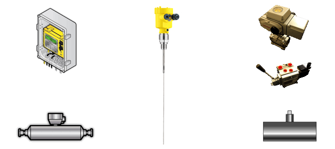
The hardware components required for the RapidDCC system include the Rapidlogger Hardware, the Coriolis flow meter, a water flow meter, a water control valve, a bulk feed gate control valve, a bulk gate position sensor, and a radar level sensor. All of the sensors have to be mechanically mounted and calibrated before the RapidDCC system can be utilized.
The software components required for the RapidDCC system include the RapidDCC software, the DCC test and setup software, and the RapidVU data acquisition software. Both the RapidDCC software and the RapidVU software have to work together in order for the Rapid Density Cruise Control system to work.
One important feature of the RapidDCC software is that it does not necessarily have to run on the same computer as the RapidVU software. The software can be run on any computer so long as they are connected to each other on the same network. This feature allows for a computer on the cement unit to run the RapidDCC software while the RapidVU program is being used some distance away in a monitoring van or office. However, both these software can be run on the same computer.
There are six main steps for installing the RapidDCC system components. The description of each of the subsystem installation is given below.
The slurry densitometer (Coriolis type) needs to be installed in a piping location as shown in Figure 3. The installation should be in the recirculate line before the bulk feed input. The densitometer should be installed in the recirculate piping upstream of the surge/bulk tank. If the slurry densitometer is not already in place then cutting and welding of the reflow line will be required. Additionally, installation flanges may also be needed. A welder and a mechanical technician will be needed for this work.
The water flow meter (turbine type) needs to be installed in a piping location as shown in Figure 4. This is in the water input line with the water flow control valve. The flow meter can be installed in the water flow line before or after the water flow control valve. The original manual water flow control valve should be kept in the line to allow for the water flow to be shut down manually.
Installation of the water flow meter will require welding and cutting of the water flow line. A welder and a mechanical technician will be needed for this work.
The water flow control valve controls the flow of water to the mixing tank. The RapidDCC system can control the water feed rate by controlling the position of the water flow control valve.
The water flow control valve should be installed on the water flow line as shown in Figure 6. The water flow control valve has a 2” NPT threaded connection on both sides. Installation of the water control valve will require welding and cutting of the water flow line. A welder and a mechanical technician will be needed for this work.
The tank level sensor should be installed against one wall of the tank. The installation should be such that the bottom of the sensor bracket is flush against the floor of the fluid tank. The splash guard bracket should be positioned such that the mixing fluid does not directly hit the radar sensor rod. The “L” shaped splash guard should be positioned between the direction of the flow rotation and the Radar level sensor Rod. This allows the level sensor measurements to be more stable and provide an accurate fluid level in the tank.
If the splash guard is installed backwards then the mixing fluid will splash around the radar wave guide rod and cause readings to be inaccurate. The tank level sensor should not be installed directly in one corner of the tank but it should be installed against one wall of the tank, at least one foot away from the corner. This allows space to spray wash the cement from the bracket and the wave guide rod after each job.
Installation of the level sensor will require drilling on the tank wall and bolting the level sensor bracket to it. A mechanical technician will be needed for this work.
The hydraulic solenoid valve controls the bulk feed gate valve. The solenoid valve is controlled by the RapidDCC software.
This solenoid valve will be installed in the place of the existing manual steering valve that is used to control the knife gate. Hydraulic pressure and tank connections from the old steering valve will have to be connected to the new Steering Valve Pressure and Tank connections. The pressure (P) and tank (T) ports are marked on the valve as shown in Figure 10. Both of these ports have a SAE#12 female connection.
Hydraulic connections to the knife gate cylinder need to be made from the work ports of the solenoid valve. The work ports are shown in Figure 11 and have a SAE#10 female connection.
Installation of the hydraulic solenoid control valve will require drilling, welding and the fabrication of hydraulic hoses or hose adapters. NPT to SAE fitting adapters may also be needed.
A mechanical technician and hydraulic hose service company will be needed for this work.
The RapidDCC system senses the position of the knife gate by means of a linear position sensor. The linear position sensor is shown in Figure 12.
A magnetic ring is mounted on the knife gate and moves with it. The sensing rod of the linear position sensor passes through the magnet. The electronics inside the linear sensor register the position of the magnet and transmit it to the Rapidlogger RapidDCC system. A locally fabricated bracket suitable for mounting the sensor will have to be installed on the hydraulic cylinder to mount the linear position sensor. This bracket will keep the linear sensor fixed parallel to the hydraulic cylinder and allow the magnet ring to move freely along it length.
Installation of the linear sensor will require welding and drilling on the mechanical brackets holding the hydraulic cylinder.
A mechanical technician and a welder will be needed for this work.
For installation of the standard Rapidlogger System please refer to the Rapidlogger Manual. For installation of the RapidDCC specific items please see below.
The RapidDCC junction box contains the power supply, control relays and wire terminals for the RapidDCC system. The power cable for the RapidDCC Junction Box needs to be connected to the truck power source (12/24V DC). The RapidDCC Junction box is permanently wired to Rapidlogger system and should be mounted to the panel near the Rapidlogger System.
The water flow meter for the RapidDCC is a turbine type flow meter. The mag pickup for the flow meter is shipped separately from the meter and needs to be screwed in to the meter. The cable simply plugs in to the water flow meter cable that is included with the system.
The water control valve is a DC servo operated ball valve with a position feedback feature. It has a terminal block inside the top of the housing. All six terminals for power, control and signal pairs need to be wired to the pre-marked wires on the water control valve cable.
The tank level sensor is a two wire guided wave radar sensor. The terminal block inside the top of the sensor housing can be access by unscrewing the top. The two terminals marked 4-20mA need to be wired to the tank level sensor cable wires.
The hydraulic solenoid valve is a double solenoid operated pilot assisted hydraulic spool valve. The electrical connection to the valve is by means of a 4 pin Deutsche connector. The appropriate connector/cable for this valve is supplied already connected to the RapidDCC Junction Box.
The knife gate position sensor is a linear hall effect sensor with a two wire 4-20 output. The connection is made via a Rota connector. The mating connector for this is already made up on the Knife gate position sensor cable. It simply needs to be plugged in to the connector
Once the hardware installation is complete the sensors need to be setup and calibrated in order to properly run the RapidDCC software. It must be noted here that the RapidDCC software requires the water flow rate, and the slurry flow rate to be in barrels per minute. The tank level is required to be in percentage and the tank volume is required to be in barrels. The slurry density has units ppg.
The water flow meter supplied with the RapidDCC system is installed in the water inflow line of the mixing tank. Its purpose is to measure the water inflow in to the mixing tank. Since the water inflow rate directly impacts the slurry density, it is important that the water flow meter be accurately calibrated.
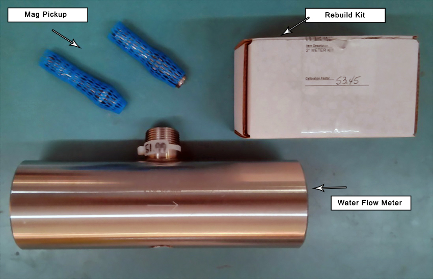
The first step in setting up the calibration of the water flow meter is to determine the flow coefficient of the meter. If the meter is new this information can be located on a tag on the meter body. For example if the number 51.99 appears on the flow meter tag it means that the turbine on this particular flow meter generates 51.99 pulses for each gallon of liquid that flows through it.
In order to calculate the multiplier to enter in the Rapidlogger for this flow meter the following calculations need to be performed.
Flow meter Coefficient = 51.99
Flow meter volume calculation:
Multiplier for Rapidlogger = 1 / Flow meter Coefficient = 1 / 51.99 = 0.01923447 gal/pulse
Flow meter flow rate calculation:
Multiplier for Rapidlogger = 1 / Flow meter Coefficient * 60 = 1 / 51.99 * 60= 1.15406809 gal/pulse/min
In case the flow meter coefficient is not known, then field measurements will have to be taken to calculate the flow meter coefficient. In order to do this a known amount of water (at least 10 barrels) would have to be pumped through the meter in to the mixing tank. The exact number of pulses registered by the flow meter on the magnetic pickup will have to be recorded. Now dividing the total volume in barrels pumped by the total number of pulses will give the Multiplier for the Rapidlogger flow meter volume. Multiplying this number by 60 (since there are 60 seconds in every minute) will yield the Multiplier for the flow meter rate.
The water flow meter has a three wire sensor. The wires for this should be connected inside the Rapidlogger on the terminal block as follows. Power wire connects to the +24V DC power out. Ground wire connects to the DC GND out. And the signal wire should be connected to the QA2 wire terminal. The cord grip should then be tightened down around the cable insulation to produce a water tight seal. Refer to Appendix D: RapidDCC Wiring for sensor wiring figures.
The second meter that is required for proper operation of the RapidDCC software is the slurry flow meter. The slurry flow meter is generally a Coriolis type flow meter. This type of meter outputs both the volumetric flow rate and the mass flow rate of the slurry. For the purpose of the RapidDCC software the volumetric flow rate signal from the meter is more important than the density measurement.
Its purpose is to measure the slurry density in the recirculate line. Since the slurry density control runs based on this density measurement, it is important that the slurry density signal from the meter be accurately calibrated.
The first step in setting up the calibration of the slurry flow meter is to setup the flow coefficient of the meter.
For Endress Hauser Promass 83 meters the Pulse Frequency Output setting should be setup as follows. The Output Pulse/Frequency configuration should be setup to have Operation Mode setup to be Frequency. The Assign Frequency setting should be setup to be Volume Flow. The Start Value Frequency setting of 0 and an End Value Frequency setting of 10000. The Value Flow High should be setup at 20BPM. With these settings the Endress Hauser Promass meter will output 10000 Hz frequency for a flow rate of 20 Barrels per minute.
For Emerson Micromotion 2700 meters the Channel B should be setup for Frequency. The setting F0 SRC should be VFLOW. The F0 Scale should be FR FL. The FREQ (Frequency Range) should be 10000. The F0 Rate should be 20 BPM. The F0 Polar should be setup to be High. With these settings the Micromotion meter will output 10000 Hz frequency for a flow rate of 20 Barrels per minute.
The slurry flow meters (both Emerson/Micromotion and the Endress Hauser) have a four wire sensor cable supplied with the RapidDCC. The power to these flow meters should be supplied on a separate cable from a power supply rated for these meters. The sensor cable wires for this should be connected inside the Rapidlogger on the terminal block as follows. Frequency ground wire connects to the DC GND terminal. Frequency signal wire should be connected to the QA1 wire terminal. The milli-ampere ground wire should be connected to the DC GND terminal. The milli-ampere signal wire should be connected to the ma3 terminal. The cord grip should then be tightened down around the cable insulation to produce a water tight seal.
The tank level sensor is the next sensor that needs to be setup before use with the RapidDCC
The Vega brand level sensor supplied with the RapidDCC system is calibrated at the factory to output 4mA at 0” of fluid level and 20mA at maximum level of 72”. The setup and programming for this sensor is done by means of a HART /USB interface with a PC and cannot be conveniently done in the field. The sensor needs to be setup for the type of tank being used (Stepped or straight tank). The level sensor supplied with the RapidDCC is preconfigured at the factory for the type of tank required (stepped or straight).
Once the sensors have been physically setup the next step is to configure the Rapidlogger unit to properly acquire data from these sensors and transmit it to the RapidVU software. These variable have already been setup at the factory in the Rapidlogger System supplied with the RapidDCC.
The calibration factors and offsets for the three sensors can be calculated and entered as shown below.
Water flow meter setup:
The water flow meter will be setup first. Start the Rapidlogger Utility program on a PC that is connected to the Rapidlogger System with an Ethernet cable.
Use the Find Rapidlogger button to verify that there is proper communication between the PC and the Rapidlogger Hardware. Use the command Read All from Unit to retrieve all setup from the Rapidlogger hardware. Use the command Write Vars File to backup these setting to a local folder on your PC. Now create a new variable number 12 and set it up exactly as follows. The Variable name should be WaterFlow, the variable units should be gpm, and the decimal places should be 1. The check boxes for Enable and Record/Transmit should be checked.
The I/O Type needs to be setup as Frequency. The Frequency Input number should be 3. The Offset should be 0. The multiplier value should be setup as follows.
Example 1: Flow meter flow rate calculation:
Flow meter Coefficient = 51.99pulses per gallon
Multiplier for Rapidlogger = 1 / Flow meter Coefficient * 60
Multiplier for Rapidlogger = 1 / 51.99 * 60 / 42 = 0.027477 bbl/pulse/min
Use the command Write One to Unit to save this variable to the Rapidlogger Unit.
Slurry flow meter setup:
The slurry flow meter will be setup next. Use the command Read All from Unit to retrieve all setup from the Rapidlogger hardware. Use the command Write Vars File to backup these setting to a local folder on your PC. Now create a new variable number 13 and set it up exactly as follows. The Variable name should be SlurryFlow, the variable units should be gpm, and the decimal places should be 1. The check boxes for Enable and Record/Transmit should be checked.
The I/O Type needs to be setup as Frequency Rate. The Input number should be 5. The Offset should be 0. The multiplier value should be setup as follows.
Example 1: Coriolis flow meter flow rate calculation:
Flow meter Max Frequency = 10000Hz
Flow meter Max Flow rate = 20 BPM
Multiplier for Rapidlogger = Max flow / Max Frequency
Multiplier for Rapidlogger = 20 / 10000 = 0.002 bbl/pulse/min
Use the command Write One to Unit to save this variable to the Rapidlogger Unit.
Level sensor setup:
The guided wave radar level sensor will be setup next. Use the command Read All from Unit to retrieve all setup from the Rapidlogger hardware. Use the command Write Vars File to backup these setting to a local folder on your PC. Now create a new variable number 14 and set it up exactly as follows. The Variable name should be LevelSensor, the variable units should be ft, and the decimal places should be 3. The check boxes for Enable and Record/Transmit should be checked.
The I/O Type needs to be setup as Analog. The Analog Input number should be 4. The Offset and multiplier should be calculated as follows.
Example 1: Guided wave radar level sensor 5 ft range
Level Sensor Min output = 4mA
Fluid height at Min output = 0%
Level Sensor Max output = 20mA
Fluid height at Max output = 100%
Level Sensor Offset Value = - Fluid height at max output / 4
Level Sensor Offset Value = - 100 / 4 = -25.0
Level Sensor Multiplier Value = 100 / (65535 – 13107)
Level Sensor Multiplier Value = 0.00190738
Use the command Write One to Unit to save this variable to the Rapidlogger Unit.
Once the sensors have been setup the next step is to install the RapidVu software and the RapidDCC software for proper operation. The RapidDCC program runs the RapidDCC control system related processes in real time. For this purpose it acquires flow rate, level, volume and time information from the Rapidlogger Unit. In order for the RapidVu and RapidDCC program to run properly the RapidVu software version should be at least 4.4.41 or higher needs to be installed and running. The version of RapidDCC program should be software version 2.4.10 or higher.
Start the RapidVu program to enable data acquisition from the Rapidlogger hardware. Test that the data acquisition works. No further setup of the RapidVu software is needed.
Now start the RapidDCC program.
Press the Setup button. Make sure that the IP address, Tank Height, Tank Volume, and Bulk cement Density is entered correctly.
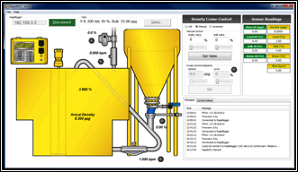
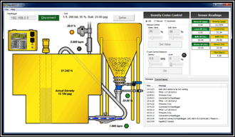
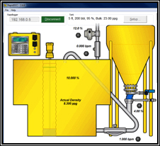
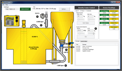
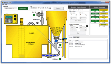
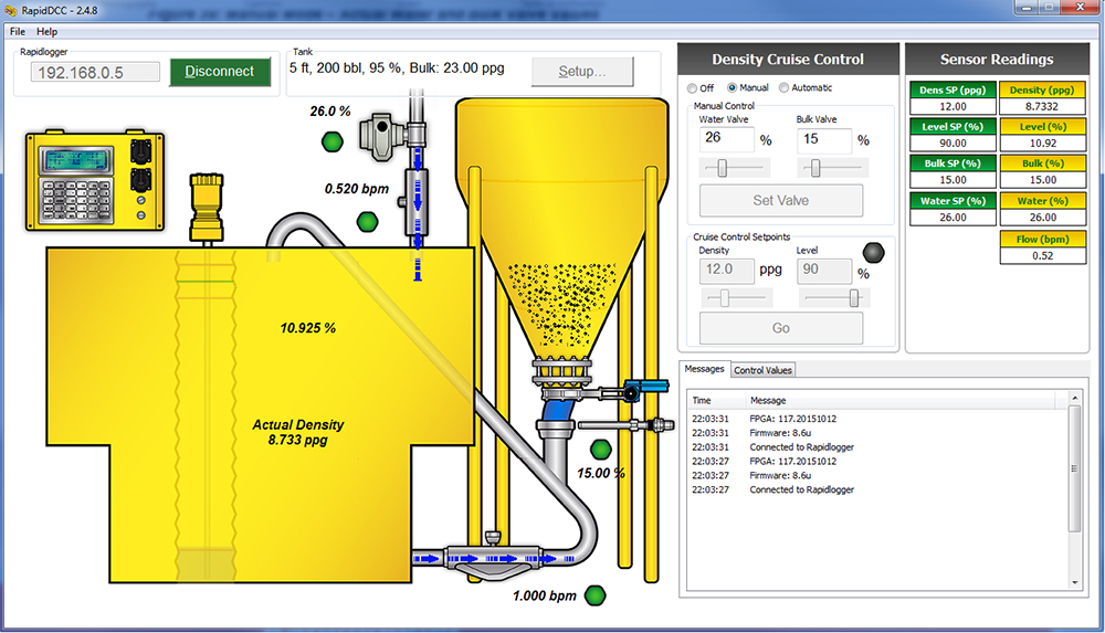
Once the hardware installation and sensor calibration is complete the following tests need to be completed. The main screen of the RapidDCC software is shown in Figure 23 with added labels for the system sensor readings displayed.
The system elements must be individually tested as follows:
Power the valve via the power switch on the external relay box. Use the RapidDCC software to control the water valve under software manual control. Water output should be able to be controlled from fully off to fully on in a proportional manner.
The built in sensor on the water control valve should clearly show its’ position on the mill-ampere analog input as actuated. When the water valve is commanded to fully open the water valve position sensor should show fully open and when it is commanded to close the water valve position sensor should show fully closed.
The water flow meter flow rate reading should be visible on the RapidVu and RapidDCC software. As the water valve opens the water flow meter should read the water rate in BPM.
The level sensor should clearly show the tank level percentage on both the RapidVu and RapidDCC software. When the tank is empty the level sensor should read 0-5%. When the tank is full the level sensor should read 95-100%.
The densitometer should correctly transmit the density to the RapidVu and RapidDCC software.
The hydraulic valve position should change as the coil is energized. The hydraulic valve connects to the Rapidlogger Relay output 1 and 2 via the external relay box. The hydraulic pump/power-pack should be ON for the hydraulic valve test. Use the RapidDCC software to control the bulk valve under software manual control. When the command is given to the hydraulic knife gate valve (bulk feed valve) to fully open it should open, when commanded to 50% it should be 50% open and similarly when it is commanded to be closed it should be closed. The operation of the hydraulic knife gate valve should be visually observed to be correct.
In the above test, the bulk valve position sensor should clearly show the position on the knife gate valve (bulk feed valve).
Diagnostic Information: If this is not the case, the software shows an error status by means of a red LED. A message is displayed in the message area – “Water valve not operational. Please verify that the power is connected.”
Diagnostic Information: If this is not the case, the software shows an error status by means of a red LED. A message is displayed in the message area – “Water flow not detected. Please verify that the water pump is on, and Water flow meter is operating properly.”
Diagnostic Information: If this is not the case, the software shows an error status by means of a red LED. A message is displayed in the message area – “Water valve not operational. Please verify power is connected.”
Diagnostic Information: If the knife gate is commanded to open to a certain value and this is not achieved within 20 seconds then the software shows an error status by means of a red LED. A message is displayed in the message area – “no movement detected on the hydraulic cylinder / knife gate. Please verify that the hydraulics are on and the sensor is operational.”
These RapidDCC System tests need to be run one time after installation of the Rapidlogger RapidDCC System. The purpose of the system tests is to ensure that the software and hardware are operating correctly together and all of the installation, setup, and calibration have been done correctly.
This test should be run in Density cruise control manual mode, which requires manual opening and closing of valves. Once the RapidDCC software is connected via Ethernet to the Rapidlogger this mode is selected in the RapidDCC software as shown in Figure 24.

When the level sensor indicates the water level to be below the low water mark (set at 5%).The system only allows water to be added to the mixing tank. No bulk cement can be added at this time. Verify this condition by running the following test:
This test should also be run in Density cruise control manual mode, which requires manual opening and closing of valves. Once the RapidDCC software is connected via Ethernet to the Rapidlogger, this mode is selected in the RapidDCC software as shown in Figure 24 located in the previous section.
When the level sensor indicates the water level to be above the high water mark (software settable, but default set at 95%). The system does not allow either the water or bulk valve to be opened because this will overflow the tank. Verify this condition by running the following test:
These steady state tests only run in Density cruise control automatic mode and do not require manual opening and closing of valves. Once the RapidDCC software is connected via Ethernet to the Rapidlogger, this mode is selected in the RapidDCC software as shown in Figure 27.
When the fluid level is above the low water mark the algorithm should build up or build down the slurry density as required by the density set point. To verify the steady state condition run the following three tests:
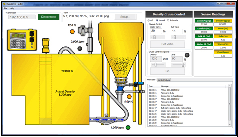
Steady State Test – Tank Half Full
Note: In this example, the Actual slurry density is about 12.2 ppg at startup so we set the Density set point to 12.0 ppg, which is approximately equal. During the test you perform, your Actual slurry density value can be different from the example. This test requires that the Density set point you enter be approximately equal to your Actual slurry density.
Steady State Test – Tank Empty
Steady State Test – Tank Full
This density test only runs in Density cruise control automatic mode and does not require manual opening and closing of valves. Once the RapidDCC software is connected via Ethernet to the Rapidlogger, this mode is selected in the RapidDCC software as shown in Figure 27 above.
When the density is too low in the tank when starting the system, the RapidDCC will compensate by initially only adding bulk and no water. To verify this condition run the following test:
This density test only runs in Density cruise control automatic mode and does not require manual opening and closing of valves. Once the RapidDCC software is connected via Ethernet to the Rapidlogger, this mode is selected in the RapidDCC software as shown in Figure 27 above.
When the density is too high in the tank when starting the system, the RapidDCC will compensate by initially only adding water and no bulk. To verify this condition run the following test:
This density test only runs in Density cruise control automatic mode and does not require manual opening and closing of valves. Once the RapidDCC software is connected via Ethernet to the Rapidlogger, this mode is selected in the RapidDCC software as shown in Figure 27 above.
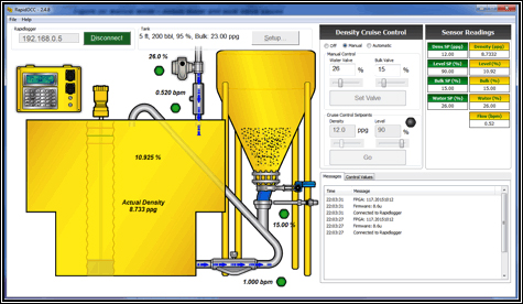
This flow out test, validates density maintenance by the system by starting with a slurry at a very high level in the tank. The system should try to achieve the density set point, while the excess fluid is overflowing from the weir gate dividing the two tanks. To verify this condition run the following test:
Once all of the setup steps in the previous sections have been completed the RapidDCC system can be run to control the automatic mixing of oilfield cement slurries.
The first step is to verify that the following setup parameters have been entered correctly:
To enter these parameters, select Setup… and a popup will appear as shown in Figure 33. These setup parameters can also be accessed by selecting File > Setup…. Enter the correct parameters for your system and then select Close.
The setup parameters will be displayed on the main RapidDCC software screen as shown in Figure 34.
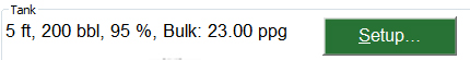
These setup parameters can only be changed while the RapidDCC software is not connected to a Rapidlogger device. If changes need to be made after a connection to a Rapidlogger device has been made, then select Disconnect.
The correct Rapidlogger IP address should be been entered in the Setup Parameters section above. To connect to the Rapidlogger device select Connect on the main screen of the RapidDCC software as shown in Figure 35.
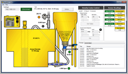
Once the connection is established and data acquisition has started the RapidDCC program indicates normal operation by flashing the screen of the small Rapidlogger Hardware device on the top left of the program as shown in Figure 36. The Connect button on the RapidDCC main screen will also be renamed to the Disconnect button and turn green as shown in the figure below. Also a “Connected to Rapidlogger” message will appear in the message area and the Sensor Readings will be read from the Rapidlogger and displayed on the RapidDCC software main screen. In the Sensor Readings section, all the readings in the left column are set points and the actual values are in the right column. If the connection failed a warning will appear and the Connect button will turn red.
Once the RapidDCC connection is successful the mode of the Density Cruise Control can be changed. The Density Cruise Control has the following three modes:
If for some reason you need to switch between Manual mode and Automatic mode or vice versa you must first select Off mode, then select Manual or Automatic mode. Never directly switch from Manual to Automatic mode or vice versa without first putting the RapidDCC system in Off mode.
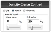
To run the RapidDCC system in manual mode the RapidDCC software must be connected via Ethernet to the Rapidlogger as described in section 8.2. This mode is selected in the RapidDCC software as shown in Figure 37.
In this mode the water and bulk valves can be controlled manually using the RapidDCC software. A job can be run in this mode without having to physically move these valves, but by controlling them from the software. Before changing the water and bulk set points you can determine the actual water and bulk values from the Sensor Readings and from the RapidDCC system image in the RapidDCC software as shown in Figure 38. In the Sensor Readings section, all the readings in the left column are set points and the actual values are in the right column.
To control the water and bulk valves enter the set points in the text boxes or use the sliders as shown in Figure 39. Once the set point(s) have been changed to the desired values select Set Valve.
The water and bulk valves set points will also be updated in the Sensor Readings. The corresponding status LEDs will turn yellow to indicate the algorithm is working to reach the set points. The water control valve takes approximately 20 seconds to go from fully closed to fully open and the bulk control valve takes approximately 15 seconds to go from fully closed to fully open.
After the RapidDCC system has some time to run the water and bulk valve set points will be reached and become the actual water and bulk valve values. Once this has happened the set points and actual values are the same and the corresponding status LEDs become green.
To run the RapidDCC system in automatic mode the RapidDCC software must be connected via Ethernet to the Rapidlogger as described in section 8.2. This mode is selected in the RapidDCC software as shown in Figure 42.

In this mode the density and level set points can be entered into the RapidDCC software. The water and bulk valves are then automatically controlled by the RapidDCC software based on the actual density and level readings and their entered set points. The Density Cruise Control algorithm will run until these set points are achieved by controlling the water and bulk valves. Once these density and level set points are achieved the RapidDCC system will steadily maintain these set points until the system is turned off or different set points are entered.
Before changing the density and level set points you can determine the actual slurry density and tank level values from the Sensor Readings and from the RapidDCC system image in the RapidDCC software as shown in Figure 43. In the Sensor Readings section, all the readings in the left column are set points and the actual values are in the right column.
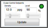
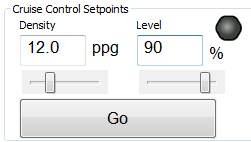
To control the slurry density and tank level, enter the set points in the text boxes or use the sliders as shown in Figure 44. Once the set point(s) have been changed to the desired values select Go.
The density and level set points will also be updated in the Sensor Readings. The Slurry Density status LED will turn yellow to indicate the algorithm is working to reach the density set point.
After the RapidDCC system has some time to run the density and level set points will be reached and become the density and level values. Once this has happened the set points and actual values are the same and the Slurry Density status LED becomes green.
The RapidDCC status LEDs help to more quickly view the status of the RapidDCC system. There are five of these status LEDs as shown in Figure 46.
All Status LEDs gray: This indicates that the RapidDCC system is in Density Cruise Control Off mode or it is not running.
In general, the status LEDs indicate:
Yellow: Running
Green: Success
Red: Failure, but still running
Yellow: This indicates that the RapidDCC system is in Density Cruise Control Automatic mode, but the density set point is not yet achieved.
Green: This indicates that the RapidDCC system is in Density Cruise Control Automatic mode and the density set point is approximately achieved.
Red: This indicates that the RapidDCC system is in Density Cruise Control Automatic mode, but the density set point has failed to be achieved within 15-20 seconds. The system will continue to try and reach the desired set point.
Green: This indicates that the flow rate is on
Red: This indicates that the flow rate is off.
Green: This indicates that the position sensor is approximately at the commanded position.
Red: This indicates that the position sensor is not at the commanded position.
Green: This indicates that the water flow meter is approximately at the set position.
Red: This indicates that the water flow meter is not at the set position.
Green: This indicates that the water control valve is approximately at the set point.
Red: This indicates that the water valve set point has failed to be achieved within 15-20 seconds. The system will continue to try and reach the desired set point.
Message Area:
The Messages tab on the bottom right of the RapidDCC main screen displays the time and text for each message. These messages convey RapidDCC system status, diagnostic and error information.
Control Values:
The Control Values tab is displayed on the bottom right of the RapidDCC main screen. These control values are only for diagnostic purposes and might be requested during technical support.
The Rapidlogger Utility is a program that can be run on a PC and allows the user to make changes to the Rapidlogger setup and configuration. It is not used in normal operation but only when there is a need to reconfigure some aspect of the Rapidlogger setup. This program has to be run on a PC that is on the same Ethernet network as the Rapidlogger Unit. It can be used to configure variables and system settings on the Rapidlogger unit.
To begin using the utility, click the button labeled “Find Rapidlogger”, after entering the unit’s IP address. If the correct IP address is entered then the presence of the unit at that address is confirmed by the software.
Changing System Settings
To begin changing system settings, click the button labeled “System Setup” to access the System Setup dialogue. In order to begin changing settings, the unit’s current settings must be retrieved by clicking the button labeled “Retrieve from Unit” button. Note that the dialog updates to reflect the Rapidlogger’s current settings.
The options available from this dialogue are:
Number of LCD Display Variables – Choose how many variables the Rapidlogger unit will display on its LCD front panel.
Operating Mode – Change the Rapidlogger’s operating mode between Cementing, Slickline, Fracturing, N2, and CT.
Recording Period – Set the frequency at which the Rapidlogger writes data to its job file. The options are data recording every 1, 5, 10, and 60 seconds.
Dial Variable – Choose the variable that will be displayed on the analog dial in the Rapid VU program.
Dial Lower/Upper Limit – Set the range that the Rapid VU dial will cover.
Analog Inputs Calibration Factor – Set the calibration multiplier for the Rapidlogger’s analog inputs. This option should be used with care. In order to recalibrate the analog inputs on a Rapidlogger Unit a precision calibrated current source is required. To prevent unintentional re-calibrations this option has have no effect unless the calibration mode is explicitly enabled on the Rapidlogger unit from the front panel.
The configuration of the two quadrature inputs on the Rapidlogger unit can be modified based on the application. In the normal mode these inputs are used to read the quadrature (A and B channels) from a quadrature or depth encoder. However by checking the option "Quadrature as Frequency mode" these two quadrature inputs can also be used as two high-speed frequency inputs. This is useful for interfacing to devices such a micro-motion and Endress-Hauser densitometers and flow computer.
Creating and Configuring Variables
All of the Rapidlogger data is based on calculations performed on input data. The results of the calculations are stored in the system variables. The settings of the input variables can be viewed and edited from the front panel and by using the PC based Rapidlogger Setup Utility.
From the main screen, the following options for variable configuration are available:
Read One / Read All From Unit – These buttons control the loading of variables from the Rapidlogger. Typically, the Read All From Unit button is clicked before making any changes, as this allows the user to retrieve and review the configuration of all variables on the Rapidlogger from within the Rapidlogger Utility.
Write One / Write All To Unit – These buttons allow new variable setups to be exported to the Rapidlogger unit. Typically, each variable will be written one at a time as it is configured, although if the user is confident in their setup, all variables may be written at one time. Note that it may take several seconds for the unit’s front panel to reflect a change in the variable setup.
Sync Time – Updates the Rapidlogger’s internal clock to reflect the time on the PC running the Rapidlogger utility.
Write Vars File – Save the current variable configuration to a location on the PC running the Rapidlogger utility. The vars file can be used to save a complex setup for later use or back up the current variable configuration. Note that writing the current configuration to a vars file does not affect the Rapidlogger unit in any way.
Read Vars File – Load a variable setup from a previously-written vars file. Note that reading a vars file does not affect the Rapidlogger unit in any way – the variables must still be written to the unit.
Variable Number – Controls which variable is currently being edited.
Variable Name – Sets the name that identifies the variable on the Rapidlogger front panel and in the Rapid VU program.
Variable Units – Determines the units (lbs, bpm, etc) that the current variable is measured in. Note that the units are a label only – the Rapidlogger unit does not automatically perform the any calculations to convert sensor data from one unit system to another. Those calculations must be set up manually using the Multiplier and Offset options.
Decimal Places – Controls how many decimal places are displayed on the Rapidlogger front panel and the Rapid VU program. Note that this setting does NOT affect the precision with which data is recorded and calculated.
Input Type – Choose what type of input this variable accepts. Most variables will be Analog, Frequency, or Frequency Total. The choice of variable type depends on the physical sensor that is being used, and affects the remaining options displayed in the Rapidlogger Utility. Other more advanced, or computed variable types are also available.
Analog Variables
Input Number – Choose which analog input channel this variable will use.
Multiplier – Change how the analog input is scaled to correspond to a certain reading in the chosen units.
Offset – Change the shift applied to analog input to correspond to a certain reading in the chosen units.
Frequency and Frequency Count Variables
Input Number – Choose which frequency input channel this variable will use. Typically, both a Frequency variable and a Frequency Count variable will be assigned to the same channel.
Multiplier – Change how the variable is scaled into the chosen units. Note that the multiplier will typically be off by a factor of 60 between a Frequency variable and its associated Frequency Count variable.
Offset – For Frequency type variables, this will almost always be 0.
Many modern cement units are equipped with a Coriolis-type densitometer (Micro Motion, Endress+Hauser, etc.). These densitometers can measure the flow-rate, volume, and density of the treatment fluid. The output from the densitometers is generally in the form of an analog output for density and a frequency output for the flow rate. These signals can be interfaced to the Rapidlogger unit and the data can be displayed and recorded. The milli-ampere outputs from the flowmeter transmitter unit can be connected to one of the milli-ampere inputs, and the frequency outputs from the flowmeter can be connected to one of the frequency inputs of the Rapidlogger. The flow and density meters from Micro Motion and Endress+Hauser allow the scaling of the output signal. These scale factors are configurable on the output transmitters made by the manufacturers. This is usually accomplished by a PC based setup program that is provided by the manufacturer of the flowmeter. The output scale factor must be known in order to properly interface the flow and density meters to the Rapidlogger.
Once these scale factors are known, the analog and frequency scale and offset settings of the relevant Rapidlogger inputs can be calculated as shown in the previous sections. Generally the flowmeter output the density on a milli-amp output and the flow rate is transmitted on a frequency output from the flowmeter transmitter. Contact the factory for more support on interfacing flowmeters to the Rapidlogger system.
The location of the Wire Terminal block inside the Rapidlogger system are shown in the above diagram. The following figure shows the wiring for the RapidDCC system to the Rapidlogger Hardware.
The Rapidlogger is equipped with a weatherproof Ethernet connector. If a cable is installed in this connector and connected to a network port, the Rapidlogger can communicate with a PC computer. Most Ethernet cables that are used are wired straight through and are meant to attach a device to an Ethernet Hub or Switch. This is the type of cable that is installed on the Rapidlogger. The second type of Ethernet cables that are used are wired in a crossover manner and are meant to connect two devices to each other without the need for a hub. A short crossover patch is supplied with the Rapidlogger and can be installed in between the Ethernet socket and cable connector.
Thus, if the installation requires the Rapidlogger to communicate with a PC through a Hub/Switch as in the majority of the cases, then the Ethernet cable should be used without any changes. If, however the installation requires the Rapidlogger to communicate with a PC without a Hub/Switch then the crossover patch should be installed inside the Rapidlogger unit.
The second part of communicating with a PC is setting up of the correct IP address, gateway address and network mask. There are two types of address setup mechanisms, automatic/dynamic/DHCP and static. The Rapidlogger unit uses static IP addresses. The current IP address and gateway address setup in the unit is displayed on the screen on the bottom left and bottom right of the screen for a few seconds after the unit is powered up. Both of these are a sequence of four three-digit numbers of the form (192.168.000.005). In order for the Rapidlogger to communicate properly with a PC over the Ethernet connection, the PC and Rapidlogger should have compatible IP addresses that are within the same subnet. If the user is unfamiliar with IP addresses then it is recommended that they use the following.
PC / Laptop
IP: 192.168.000.001
Gateway: 192.168.000.001
Netmask: 255.255.255.000
Rapidlogger
IP: 192.168.000.005
Gateway: 192.168.000.001
Netmask: 255.255.255.000
IP settings on a PC are done from the Windows control panel in the IP setting field within the properties of the LAN Connection Dialog box. On the Rapidlogger these settings are done from the front panel keypad. Press F6, F6, F1 and then enter the IP address, Gateway and Netmask when prompted on the screen. Perform a power cycle to verify and activate the IP address from the LCD screen. The default IP address of 192.168.000.005 is setup in the system at the factory. This is also the IP address that the system goes back to whenever a factory reset is done. Advanced users should select and utilize the IP addresses appropriate for their network.
Once the IP addresses are setup then the PC and the Rapidlogger are able to communicate with each other. Proper communication can be verified by performing a PING from the PC to the Rapidlogger IP address. Do note that some PC firewall programs block Ethernet communication that they are not familiar with. If you have such a firewall running on your PC then you may either need to disable it or specifically setup it up to allow full two way communication to the Rapidlogger IP Address.
