Pressure is perhaps the most measured parameter in the oilfield. Oilfield pressure sensors can be installed on pressure lines with threaded connections, wing unions, or swageloc fittings. Some examples of the different pressures that are measured in the oilfield are; wellhead pressure, pumping pressure, suction pressure, and hydraulic pressure.
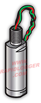
Most oilfield pressure sensors operate with strain gages. A metallic diaphragm in the sensor is exposed to pressurized fluid on one side and atmospheric pressure on the other side. Fluid or gas pressure on the wet side of the diaphragm deflects the diaphragm and strain gages mounted on the dry side measure the deflection. Sometimes an amplifier is built in to the pressure sensor to improve the quality of the pressure signal. Pressure sensor electrical signals can be fed directly in to the Rapidlogger System and recorded.
The strain gage configuration typically uses a Wheatstone bridge circuit, where four strain gages are arranged to maximize sensitivity and minimize temperature effects. As pressure is applied, the diaphragm flexes, causing two of the gages to be stretched (increasing resistance) while the other two are compressed (decreasing resistance). This creates a differential voltage output proportional to the applied pressure.
Common Pressure Ranges: Oilfield pressure sensors are available in ranges from 0-100 psi for low-pressure applications up to 0-20,000 psi for high-pressure fracturing and drilling operations. The most common ranges are 0-5,000 psi and 0-10,000 psi for wellhead and pumping applications.
Output Signals: Standard output signals include 4-20 mA current loop (industry standard), 0-5 VDC, 0-10 VDC, and millivolt outputs from strain gage bridges. The 4-20 mA signal is preferred for long cable runs due to its superior noise immunity.
Accuracy and Resolution: Typical accuracy ranges from ±0.25% to ±1.0% of full scale. High-precision sensors can achieve ±0.1% accuracy. Resolution depends on the data acquisition system but typically ranges from 12-bit to 16-bit, providing resolution of 0.02% to 0.0015% of full scale.
Response Time: Pressure sensors have fast response times, typically less than 10 milliseconds, making them suitable for capturing rapid pressure transients during pumping operations.
Fracturing Operations: Multiple pressure sensors monitor treating pressure, suction pressure at each pump, wellhead pressure, and annulus pressure. Real-time pressure data is critical for detecting screenouts, monitoring proppant delivery, and ensuring safe operation within equipment limits.
Cementing Services: Pressure monitoring during cement jobs helps ensure proper cement placement and detects channeling or lost circulation. Pressure trends indicate when cement reaches specific zones and when displacement is complete.
Well Testing: Bottomhole pressure sensors and surface pressure measurements are used to determine reservoir properties, flow rates, and well productivity. Pressure buildup and drawdown tests provide critical reservoir characterization data.
Coiled Tubing: Injection pressure, wellhead pressure, and hydraulic power pack pressure are monitored continuously to optimize coiled tubing operations and ensure equipment safety.
Installation Guidelines: Pressure sensors should be installed in locations that minimize vibration and are easily accessible for maintenance. Use proper torque specifications for threaded sensors (typically 30-50 ft-lbs depending on size) to prevent leaks while avoiding overtightening that can damage the sensor housing.
Mounting Considerations: Install sensors away from pump vibration sources when possible. Use isolation valves to allow sensor removal without system shutdown. Ensure proper venting of gas-trapped systems and use pulsation dampeners for high-frequency pressure fluctuations.
Wiring and Signal Integrity: Use shielded cables for analog signals to minimize electrical noise. Separate sensor cables from high-voltage power lines. For long cable runs exceeding 500 feet, 4-20 mA current loop outputs are recommended over voltage outputs.
Calibration Procedures: Pressure sensors should be calibrated using deadweight testers or precision pressure calibrators traceable to NIST standards. Perform zero and span calibration at minimum. Multi-point calibration (typically 0%, 25%, 50%, 75%, 100% of range) provides better linearity verification. Recalibrate sensors annually or after exposure to overpressure events.
Zero Adjustment: With no pressure applied and sensor at ambient temperature, adjust zero offset to read zero pressure. Allow sensors to stabilize for 15-30 minutes before zero calibration to eliminate thermal drift effects.
API Standards: Pressure measurement in oilfield operations should comply with API RP 13D for drilling fluid testing and API RP 39 for well control equipment testing. These standards specify accuracy requirements, calibration intervals, and documentation procedures.
NACE Compliance: Sensors in corrosive environments should meet NACE MR0175/ISO 15156 standards for materials selection to prevent sulfide stress cracking and hydrogen embrittlement in sour service.
Electrical Classification: Sensors installed in hazardous locations must be rated for the appropriate electrical classification (Class I, Division 1 or 2, Groups B, C, D). Intrinsically safe (IS) sensors are commonly used in Zone 0 and Zone 1 locations.
Pressure Equipment Directive (PED): For operations in European markets, pressure sensors must comply with PED 2014/68/EU requirements for pressure-bearing equipment.
Calibration Traceability: All calibration equipment must be traceable to NIST (National Institute of Standards and Technology) or equivalent international standards organizations such as NPL (UK) or PTB (Germany). Maintain calibration certificates and documentation for regulatory compliance and quality assurance.
