Density of fluids is an important parameter to measure in the oilfield. Everything from cement to drilling mud requires a good measure of density.
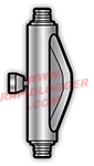
Two of the most common type of oilfield densitometers are the radioactive and Coriolis types. Densitometer based on the Coriolis principal utilize a 'U' shaped tube in the flow. Actuators built into the meter vibrate the bent tube perpendicular to the direction of flow. The Coriolis effect forces a twist in the vibrating tube. The amount of twist is measured and is proportional to the mass flow through the tube.
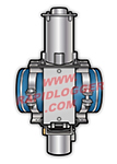
The radioactive densitometer works by means of a radioactive source. The source sends out gamma rays through the pipe and the fluid inside. The gamma rays pass through the pipe and fluid and hit a detector. The detector measures the intensity of the gamma radiation which is proportional to the density of the fluid.
Coriolis Mass Flow Meters: These meters measure density as a secondary parameter while primarily measuring mass flow. The vibrating tube's resonant frequency changes with fluid density. By measuring frequency shift and tube twist simultaneously, the meter calculates both mass flow rate and fluid density. Coriolis meters provide exceptional accuracy (±0.001 g/cm³) and are ideal for clean fluids in enclosed systems.
Nuclear (Gamma Ray) Densitometers: Use radioactive isotopes (typically Cesium-137 or Cobalt-60) to emit gamma radiation through the process fluid. The intensity of radiation reaching the detector is inversely proportional to fluid density. Nuclear densitometers work well with slurries, multiphase flows, and high-viscosity fluids. They are non-invasive and can be installed on existing pipes without cutting or welding.
Vibrating Fork Density Sensors: Use a tuning fork element vibrating at its resonant frequency. When immersed in fluid, the resonant frequency changes based on fluid density. These sensors are simple, rugged, and economical for point-level and density monitoring in tanks and process vessels.
Hydrostatic Pressure Densitometers: Calculate density by measuring pressure difference between two vertical points in a vessel. Density equals pressure differential divided by the vertical distance and gravitational constant. Simple and reliable but requires vertical installation and is sensitive to level variations.
Microwave Density Sensors: Transmit microwave signals through the fluid and measure phase shift or attenuation. The dielectric properties of the fluid affect microwave propagation. These sensors are non-radioactive alternatives to nuclear densitometers for certain applications.
Density Range: Oilfield density sensors typically measure from 0.5 to 3.0 g/cm³ (4.2 to 25 lb/gal) to cover water, oil, drilling mud, and cement slurries. Extended range instruments can measure up to 5.0 g/cm³ for heavy muds and barite-laden fluids.
Accuracy: Coriolis meters: ±0.0005 to ±0.001 g/cm³; Nuclear densitometers: ±0.005 to ±0.02 g/cm³; Vibrating fork sensors: ±0.01 to ±0.02 g/cm³; Hydrostatic methods: ±0.02 to ±0.05 g/cm³. Accuracy depends on temperature stability, calibration, and fluid properties.
Repeatability: Coriolis meters offer exceptional repeatability of ±0.0002 g/cm³. Nuclear densitometers provide ±0.002 to ±0.005 g/cm³ repeatability. Good repeatability is essential for process control even if absolute accuracy is moderate.
Response Time: Coriolis meters: 1-5 seconds; Nuclear densitometers: 1-30 seconds depending on source strength and statistics settings; Vibrating element sensors: 1-10 seconds. Faster response enables tighter process control but may sacrifice stability.
Temperature Compensation: All density measurements are temperature-dependent. High-quality instruments include automatic temperature compensation using integrated RTD sensors. Temperature correction is critical for accurate density measurement, as fluids typically change density by 0.0005 to 0.002 g/cm³ per °F.
Output Signals: Standard outputs include 4-20 mA proportional to density, digital protocols (Modbus, HART, Foundation Fieldbus), and relay outputs for density alarms. Some instruments provide simultaneous mass flow, density, and temperature outputs.
Drilling Mud Control: Real-time density monitoring ensures proper mud weight for wellbore stability and pressure control. Density must be maintained within tight specifications (typically ±0.1 to ±0.3 lb/gal) to prevent kicks, lost circulation, and differential sticking. Automated mixing systems use density feedback to control barite addition rates.
Cementing Operations: Accurate density measurement is critical during cement mixing and pumping. Lead and tail cement densities must meet design specifications to ensure proper zonal isolation. Density monitoring detects mixing inconsistencies, identifies contamination, and verifies proper cement placement. API specifications require density accuracy of ±0.2 lb/gal for cement slurries.
Fracturing Fluid Blending: Density sensors monitor proppant loading in real-time during fracturing operations. Consistent slurry density ensures proper proppant transport and placement. Nuclear densitometers are preferred for measuring abrasive proppant slurries that would damage Coriolis meters.
Production Separation: Density measurement in separators helps determine oil/water/gas ratios. Three-phase separators use multiple density measurements to optimize separation efficiency and detect upsets. Density difference between oil and water phases drives level control in gravity separators.
Pipeline Batch Monitoring: Density sensors detect interface between different crude grades, products, or batches in pipelines. Interface detection enables automated valve control and minimizes product contamination during batch changes.
Coriolis Meter Installation: Mount meters with proper pipe support before and after the meter to prevent stress. Allow straight pipe runs per manufacturer specifications (typically 0-3 diameters upstream). Install meters horizontally or vertically with upward flow for liquid service to ensure complete filling. Avoid locations with excessive vibration or pulsating flow.
Nuclear Densitometer Installation: Position source and detector on opposite sides of pipe with proper alignment. Maintain required spacing based on pipe diameter and fluid density range. Install radiation shields and warning signs per radiation safety requirements. Secure source and detector mounts to prevent misalignment from vibration. Ensure detector cable is properly shielded and grounded.
Safety Requirements for Radioactive Sources: Comply with NRC (Nuclear Regulatory Commission) or equivalent national authority licensing requirements. Appoint qualified radiation safety officer. Implement radiation monitoring program with dosimeters and area surveys. Maintain source leak tests and inventory records. Post radiation warning signs and restricted area barriers. Provide radiation safety training for personnel.
Calibration Methods: Calibrate density sensors using certified reference fluids with known densities traceable to NIST standards. For Coriolis meters, use water and one or more hydrocarbon standards spanning the operating range. For nuclear densitometers, calibrate with fluids matching expected process conditions. Perform multi-point calibration at operating temperature.
Field Verification: Verify Coriolis meters by comparing readings with lab-analyzed samples. Check nuclear densitometer response using pipe-full and pipe-empty conditions. Verify temperature compensation by measuring known fluids at different temperatures. Document verification results and maintain calibration history.
Maintenance: Inspect Coriolis meters for external damage, corrosion, and cable integrity. Clean tubes if fouling is suspected (back-flush or chemical cleaning). For nuclear densitometers, verify source and detector alignment, check detector voltage, and test electronics. Replace detector tubes per manufacturer specifications (typically 5-10 years). Perform radiation surveys annually.
API RP 13B-1: Recommended Practice for Field Testing of Water-Based Drilling Fluids specifies mud density measurement procedures and accuracy requirements. Requires density measurement within ±0.1 lb/gal for quality control.
API Spec 10A: Specification for Cements and Materials for Well Cementing includes density measurement requirements for cement slurries. Specifies standardized testing procedures and reporting formats.
ISO 11631: Measurement of fluid flow - Methods of specifying flowmeter performance provides standards for Coriolis meter performance specifications and testing.
NIST Handbook 44: Specifications, tolerances, and technical requirements for commercial weighing and measuring devices includes requirements for mass flow meters and densitometers used in custody transfer.
Nuclear Regulatory Requirements: In the United States, radioactive source gauges are regulated by NRC under 10 CFR Part 30 (Byproduct Material Licenses) and Part 20 (Radiation Protection Standards). State radiation control programs may have additional requirements. International regulations include IAEA Safety Standards and national nuclear authorities.
DOT Regulations: Transportation of radioactive sources must comply with DOT 49 CFR Parts 170-189 and IAEA Transport Regulations. Requires proper packaging, labeling, documentation, and carrier certification.
ATEX/IECEx Compliance: Density sensors for hazardous areas must carry appropriate certifications. Coriolis meters require explosion-proof or intrinsically safe designs. Nuclear densitometers must meet electrical classification requirements for all electronic components.
Pressure Vessel Certification: Coriolis meter flow tubes are pressure vessels requiring ASME certification for high-pressure applications (typically above 3,000 psi). Material selection must comply with NACE MR0175 for sour service environments.
