Copyright 2015, Rapidlogger Systems
www.rapidlogger.com
Table of Contents
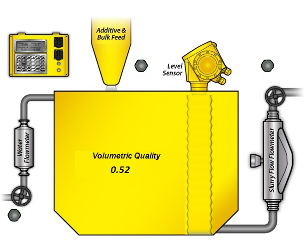
The Rapidlogger RapidVQI is a Volumetric mixing quality indicator system for mixing oilfield fluids, dry/wet additives, gels, sands and cements without the need for a densitometer. The system operates by means of calculating the inflow of the base fluid (water, brine, acid) and the total increase in the tank level of the combined mixture.
Any increase in the tank level beyond the metered inflow of the base fluid is assumed to be due to the addition of secondary components. While any decrease in the level is assumed to be due to the mixture being pumped out. The algorithm keeps track of the volume ratios of the base fluid to the secondary component at all times and displays them on the program screen. Details of the calculation algorithm can be reviewed in the Appendix A.
The hardware components required for the RapidVQI system include the Rapidlogger Hardware, the Coriolis flow meter, a water flow meter and a radar level sensor. All of the sensors have to be mechanically mounted and calibrated before the RapidVQI system can be utilized.
The software components required for the RapidVQI system include the RapidVQI software and the RapidVU data acquisition software. Both software have to work together to allow the Volumetric Quality Indicator system to work.
One important feature of the RapidVQI software is that it does not necessarily have to run on the same computer as the RapidVU software. But can be run on any computer so long as they are connected to each other on the same network. This feature allows for a computer on the cement unit to run the RapidVQI software while the RapidVU program is being used some distance away in a monitoring van or office.
There are two main steps for installing the RapidVQI components.
The water and slurry flow meters need to be installed in piping locations as shown in Figure 3. The water flow meter should be installed such that all the water entering the tank should pass through the meter. If some of this water is diverted to wetting the aggregate then this water should be diverted after it has been metered by the water flow meter. The slurry flow meter should be installed such that all out going mix slurry should pass through the slurry flow meter. The water valve should always be used fully opened and fully closed when using the RapidVQI system.
The tank level sensor should be installed against one wall of the tank. The installation should be such that the bottom of the sensor bracket is flush against the floor of the fluid tank. The splash guard bracket should be positioned such that the mixing fluid does not directly hit the radar sensor rod. The “L” shaped splash guard should be positioned between the direction of the flow rotation and the Radar level sensor Rod. This allows the level sensor measurements to be more stable and accurate fluid level in the tank.
If the splash guard in installed backwards then the mixing fluid will splash around the radar wave guide rod and cause readings to be in accurate. The tank level sensor should not be installed directly in one corner of the tank but it should be installed against one wall of the tank, at least one foot away from the corner. This allows ample room to spray wash the cement from the bracket and the wave guide rod after each mixing job is complete.
Once installation is complete the sensors need to be setup and calibrated in order to properly run the RapidVQI software. It must be noted here that the RapidVQI software requires the water flow rate, and the slurry flow rate to be in gallons per minute. The tank level is required to be in feet and the tank volume is required to be in gallons. The volumetric quality is a ratio of secondary component to that of water in the slurry or mix. This volumetric quality has no units. For example a volumetric quality factor of 0.3 means that in every gallon of slurry there is 0.7 gallons of water and the rest is
The water flow meter supplied with the RapidVQI system is installed in the water inflow line of the mixing tank. Its purpose is to measure the water inflow in to the mixing tank. Since the water inflow rate directly correlates to the Volumetric Quality of the slurry, it is important that the water flow meter be accurately calibrated.
The first step in setting up the calibration of the water flow meter is to determine the flow coefficient of the meter. If the meter is new this information can be located on a tag on the meter body. For example if the number 51.99 appears on the flow meter tag it means that the turbine on this particular flow meter generates 51.99 pulses for each gallon of liquid that flows through it.
In order to calculate the multiplier to enter in the Rapidlogger for this flow meter the following calculations need to be performed.
Flow meter Coefficient = 51.99
Flow meter volume calculation:
Multiplier for Rapidlogger = 1 / Flow meter Coefficient = 1 / 51.99 = 0.01923447 gal/pulse
Flow meter flow rate calculation:
Multiplier for Rapidlogger = 1 / Flow meter Coefficient * 60 = 1 / 51.99 * 60= 1.15406809 gal/pulse/min
In case the flow meter coefficient is not known then field measurements will have to be taken to calculate the flow meter coefficient. In order to do this a known amount of water (at least 10 barrels) would have to be pumped through the meter in to the mixing tank. The exact number of pulses registered by the flow meter on the magnetic pickup will have to be recorded. Now dividing the total volume in gallons pumped by the total number of pulses will give the Multiplier for the Rapidlogger flow meter volume. Multiplying this number by 60 (since there are 60 seconds in every minute) will yield the Multiplier for the flow meter rate.
The water flow meter has a three wire sensor. The wires for this should be connected inside the Rapidlogger on the terminal block as follows. Power wire connects to the +24V DC power out. Ground wire connects to the DC GND out. And the signal wire should be connected to the QA2 wire terminal. The cord grip should then be tightened down around the cable insulation to produce a water tight seal.
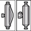
The second meter that is required for proper operation of the RapidVQI software is the slurry flow meter. The slurry flow meter is generally a Coriolis type flow meter. This type of meter outputs both the volumetric flow rate and the mass flow rate of the slurry. For the purpose of the RapidVQI software the volumetric flow rate signal from the meter is more important than the density measurement.
Its purpose is to measure the slurry outflow from the mixing tank. Since the slurry out flow rate directly correlates to the Volumetric Quality of the slurry, it is important that the slurry flow signal from the meter be accurately calibrated.
The first step in setting up the calibration of the slurry flow meter is to setup the flow coefficient of the meter.
For Endress Hauser Promass 83 meters the Pulse Frequency Output setting should be setup as follows. The Output Pulse/Frequency configuration should be setup to have Operation Mode setup to be Frequency. The Assign Frequency setting should be setup to be Volume Flow. The Start Value Frequency setting of 0 and an End Value Frequency setting of 10000. The Value Flow High should be setup at 20BPM. With these settings the Endress Hauser Promass meter will output 10000 Hz frequency for a flow rate of 20 Barrels per minute.
For Emerson Micromotion 2700 meters the Channel B should be setup for Frequency. The setting F0 SRC should be VFLOW. The F0 Scale should FR FL. The FREQ (Frequency Range) should be 10000. The F0 Rate should be 20 BPM. The F0 Polar should be setup to be High. With these settings the Micromotion meter will output 10000 Hz frequency for a flow rate of 20 Barrels per minute.
The slurry flow meters (both Emerson/Micromotion and the Endress Hauser) have a four wire sensor cable supplied with the RapidVQI. The power to these flow meters should be supplied on a separate cable from a power supply rated for these meters. The sensor cable wires for this should be connected inside the Rapidlogger on the terminal block as follows. Frequency ground wire connects to the DC GND terminal. Frequency signal wire should be connected to the QA1 wire terminal. The milli-ampere ground wire should be connected to the DC GND terminal. The milli-ampere signal wire should be connected to the ma3 terminal. The cord grip should then be tightened down around the cable insulation to produce a water tight seal.
The tank level sensor is the next sensor that is required to be calibrated for operation with the RapidVQI
The Ametek Impulse Series level sensor supplied with the RapidVQI system is calibrated at the factory to output 4mA at 0” of fluid level and 20mA at maximum level of 60” or 72”. The setup and programming for this sensor is done by means of a HART interface with a PC and cannot be conveniently done in the field.
Once the sensors have been physically setup the next step is to configure the Rapidlogger unit to properly acquire data from these sensors and transmit it to the RapidVU software. The calibration factors and offsets for the three sensors will be calculated and entered in this step. This will be done using the Rapidlogger utility.
Water flow meter setup:
The water flow meter will be setup first. Start the Rapidlogger Utility program on a PC that is connected to the Rapidlogger System with an Ethernet cable.
Use the Find Rapidlogger button to verify that there is proper communication between the PC and the Rapidlogger Hardware. Use the command Read All from Unit to retrieve all setup from the Rapidlogger hardware. Use the command Write Vars File to backup these setting to a local folder on your PC. Now create a new variable number 12 and set it up exactly as follows. The Variable name should be WaterFlow, the variable units should be gpm, and the decimal places should be 1. The check boxes for Enable and Record/Transmit should be checked.
The I/O Type needs to be setup as Quadrature Rate. The Quadrature Input number should be 2. The Offset should be 0. The multiplier value should be setup as follows.
Example 1: Flow meter flow rate calculation:
Flow meter Coefficient = 51.99pulses per gallon
Multiplier for Rapidlogger = 1 / Flow meter Coefficient * 60
Multiplier for Rapidlogger = 1 / 51.99 * 60 = 1.15406809 gal/pulse/min
Example 2: Flow meter flow rate calculation:
Flow meter Coefficient = 21.2pulses per gallon
Multiplier for Rapidlogger = 1 / Flow meter Coefficient * 60
Multiplier for Rapidlogger = 1 / 21.2 * 60 = 2.830188679 gal/pulse/min
Use the command Write One to Unit to save this variable to the Rapidlogger Unit.
Slurry flow meter setup:
The slurry flow meter will be setup next. Use the command Read All from Unit to retrieve all setup from the Rapidlogger hardware. Use the command Write Vars File to backup these setting to a local folder on your PC. Now create a new variable number 13 and set it up exactly as follows. The Variable name should be SlurryFlow, the variable units should be gpm, the decimal places should be 1. The check boxes for Enable and Record/Transmit should be checked.
The I/O Type needs to be setup as Quadrature Rate. The Quadrature Input number should be 1. The Offset should be 0. The multiplier value should be setup as follows.
Example 1: Coriolis flow meter flow rate calculation:
Flow meter Max Frequency = 10000Hz
Flow meter Max Flow rate = 20 BPM
Gallons in 1 Barrel = GperB = 42
Multiplier for Rapidlogger = Max flow / Max Frequency * GperB
Multiplier for Rapidlogger = 20 / 10000 * 42 = 0.084 gal/pulse/min
Example 2: Flow meter flow rate calculation:
Flow meter Max Frequency = 1000Hz
Flow meter Max Flow rate = 5 BPM
Gallons in 1 Barrel = GperB = 42
Multiplier for Rapidlogger = Max flow / Max Frequency * GperB
Multiplier for Rapidlogger = 5 / 1000 * 42 = 0.21 gal/pulse/min
Use the command Write One to Unit to save this variable to the Rapidlogger Unit
Level sensor setup:
The guided wave radar level sensor will be setup next. Use the command Read All from Unit to retrieve all setup from the Rapidlogger hardware. Use the command Write Vars File to backup these setting to a local folder on your PC. Now create a new variable number 14 and set it up exactly as follows. The Variable name should be LevelSensor, the variable units should be ft, the decimal places should be 3. The check boxes for Enable and Record/Transmit should be checked.
The I/O Type needs to be setup as Analog. The Analog Input number should be 4. The Offset and multiplier should be calculated as follows.
Example 1: Guided wave radar level sensor 5 ft range
Level Sensor Min output = 4mA
Fluid height at Min output = 0ft
Level Sensor Max output = 20mA
Fluid height at Max output = 5ft
Level Sensor Offset Value = - Fluid height at max output / 4
Level Sensor Offset Value = - 5 / 4 = -1.25
Level Sensor Multiplier Value = Level Sensor Max fluid height / (65535 – 13107)
Level Sensor Multiplier Value = 0.000095370
Example 2: Guided wave radar level sensor 8 ft range
Level Sensor Min output = 4mA
Fluid height at Min output = 0ft
Level Sensor Max output = 20mA
Fluid height at Max output = 8ft
Level Sensor Offset Value = - Fluid height at max output / 4
Level Sensor Offset Value = - 8 / 4 = -2.0
Level Sensor Multiplier Value = Level Sensor Max fluid height / (65535 – 13107)
Level Sensor Multiplier Value = 0.00015259
Use the command Write One to Unit to save this variable to the Rapidlogger Unit.
Volumetric Quality Variable setup:
The calculations on Volumetric Quality performed by the RapidVQI program can be stored back in the job data file and job report. This is done by creating an empty variable named ActualSlurry in the Rapidlogger Hardware. Create a new variable number 15 and set it up exactly as follows. The Variable name should be ActualSlurry, the variable units should be NA, the decimal places should be 2. The check boxes for Enable and Record/Transmit should be checked.
The I/O Type needs to be setup as CalculatedScaled. The Input number should be 1. The Offset and multiplier should both be 0.
Once the sensors have been setup the next step is to configure the RapidVU software and the RapidVQI software for proper operation. The RapidVQI program runs the Volumetric Quality Calculations in real time. For this purpose it acquires flow rate, level, volume and time information from the RapidVU program. In order to properly send data to the RapidVQI program the RapidVU software version 4.0.0 or higher needs to be installed and running. The version of RapidVQI program should be software version 1.2.13 or higher.
Start the RapidVU program, enable data acquisition from the Rapidlogger hardware. Now view the variables listed in the left side of the screen. These should include WaterFlow, SlurryFlow and LevelSensor. If this is not the case then please review the setup of the Rapidlogger hardware that was performed in the previous section.
Now start the RapidVQI program. Enter the following information correctly.
Tank Volume: This is the actual tank volume in US gallons at the maximum tank fluid level. There are 42 US gallons in one oilfield barrel.
Tank Height: This is the maximum fluid level that the tank can hold at the maximum volume capacity. This value is required in feet.
Desired Slurry: This is the volumetric ratio of the main fluid to the dry and liquid additives. This can be a unit less number between 0 and 1. For pure fluid the value is 0. For a 50/50 volumetric ratio of the fluid to the additives this value is 0.5.
Initial Slurry: This is the volumetric ratio of any initial mixed fluid in the tank. This is useful if the RapidVQI program is started in the middle of a mixing operation.
Pressing the update button on the RapidVQI screen will record these settings in the PC and these will be available automatically the next time the software is started.
Once all of the setup steps in the previous sections have been completed the RapidVQI system can be run to operate volumetric quality mixing. The first step is to make sure that the tank volume and the tank height has been entered correctly. Then enter the desired slurry quality. Press the update button. Now in order to start the RapidVQI calculations, click on the menu option Data. A dialog box with the connect option will appear.
Do not change the RapidVU Host address in this dialog and simply click on the Connect button. The RapidVU Host address should only be changed by advanced users that are using the RapidVU and RapidVQI programs on two separate computers. Once the connection is established and data acquisition has started the RapidVQI program indicates normal operation by flashing the screen of the small Rapidlogger Hardware unit on the top left of the program as shown in the figure below.
The tank level should be close to zero if the tank is empty. If the tank level shown on the screen does not match the approximate tank level in the tank. Then the level sensor rod needs to be cleaned. It is possible that mud or cement was not properly washed from the sensor rod after the previous mixing operation.
In order to start the mixing the operator should open the water flow valve and add water to at least ¼ of the level of the tank. At this time the operator should add start mixing and start adding bulk and liquid additives. As the mix tank level increases due to the addition of the bulk additives the volumetric quality number will start to increase also.
The addition of the bulk additives and water can be done simultaneously and the RapidVQI software calculates the proper proportions based on the flow meter and tank level reading.
Once the Volumetric Quality number increases up to a value near the desired Volumetric Quality the operator can start using the slurry. This slurry will flow out through the slurry flow meter and its flowrate is available to the RapidVQI software. Based on calculation the RapidVQI software will keep track of the incoming and outgoing liquid volumes and infer the addition of bulk additives from the tank level changes.
In order for the VQI mixing to be accurate the water control valve should not be opened a small amount. Rather it should be opened at least half way or completely closed. This is because volume flow rate of the incoming water is needs to be at least 20-40 gpm for the water flow meter to perform accurately. And the 2” turbine flow meter normally supplied with the RapidVQI system is less accurate at lower flow rates.
After completion of the mixing operation the guided wave radar level sensor should be thoroughly washed so that no mud cakes or cement plugs are formed on it. As these will keep the sensor from operating properly the next time it is used. Details of the software algorithm utilized in the RapidVQI software are given in the Appendix.
The Rapidlogger Utility is a program that can be run on a PC and allows the user to make changes to the Rapidlogger setup and configuration. It is not used in normal operation but only when there is a need to reconfigure some aspect of the Rapidlogger setup. This program has to be run on a PC that is on the same Ethernet network as the Rapidlogger Unit. It can be used to configure variables and system settings on the Rapidlogger unit.
To begin using the utility, click the button labeled “Find Rapidlogger”, after entering the unit’s IP address. If the correct IP address is entered then the presence of the unit at that address is confirmed by the software.
Changing System Settings
To begin changing system settings, click the button labeled “System Setup” to access the System Setup dialogue. In order to begin changing settings, the unit’s current settings must be retrieved by clicking the button labeled “Retrieve from Unit” button. Note that the dialog updates to reflect the Rapidlogger’s current settings.
The options available from this dialogue are:
Number of LCD Display Variables – Choose how many variables the Rapidlogger unit will display on its LCD front panel.
Operating Mode – Change the Rapidlogger’s operating mode between Cementing, Slickline, Fracturing, N2, and CT.
Recording Period – Set the frequency at which the Rapidlogger writes data to its job file. The options are data recording every 1, 5, 10, and 60 seconds.
Dial Variable – Choose the variable that will be displayed on the analog dial in the Rapid VU program.
Dial Lower/Upper Limit – Set the range that the Rapid VU dial will cover.
Analog Inputs Calibration Factor – Set the calibration multiplier for the Rapidlogger’s analog inputs. This option should be used with care. In order to recalibrate the analog inputs on a Rapidlogger Unit a precision calibrated current source is required. To prevent unintentional re-calibrations this option has have no effect unless the calibration mode is explicitly enabled on the Rapidlogger unit from the front panel.
The configuration of the two quadrature inputs on the Rapidlogger unit can be modified based on the application. In the normal mode these inputs are used to read the quadrature (A and B channels) from a quadrature or depth encoder. However by checking the option "Quadrature as Frequency mode" these two quadrature inputs can also be used as two high-speed frequency inputs. This is useful for interfacing to devices such a micro-motion and Endress-Hauser densitometers and flow computer.
Creating and Configuring Variables
All of the Rapidlogger data is based on calculations performed on input data. The results of the calculations are stored in the system variables. The settings of the input variables can be viewed and edited from the front panel and by using the PC based Rapidlogger Setup Utility.
From the main screen, the following options for variable configuration are available:
Read One / Read All From Unit – These buttons control the loading of variables from the Rapidlogger. Typically, the Read All From Unit button is clicked before making any changes, as this allows the user to retrieve and review the configuration of all variables on the Rapidlogger from within the Rapidlogger Utility.
Write One / Write All To Unit – These buttons allow new variable setups to be exported to the Rapidlogger unit. Typically, each variable will be written one at a time as it is configured, although if the user is confident in their setup, all variables may be written at one time. Note that it may take several seconds for the unit’s front panel to reflect a change in the variable setup.
Sync Time – Updates the Rapidlogger’s internal clock to reflect the time on the PC running the Rapidlogger utility.
Write Vars File – Save the current variable configuration to a location on the PC running the Rapidlogger utility. The vars file can be used to save a complex setup for later use or back up the current variable configuration. Note that writing the current configuration to a vars file does not affect the Rapidlogger unit in any way.
Read Vars File – Load a variable setup from a previously-written vars file. Note that reading a vars file does not affect the Rapidlogger unit in any way – the variables must still be written to the unit.
Variable Number – Controls which variable is currently being edited.
Variable Name – Sets the name that identifies the variable on the Rapidlogger front panel and in the Rapid VU program.
Variable Units – Determines the units (lbs, bpm, etc) that the current variable is measured in. Note that the units are a label only – the Rapidlogger unit does not automatically perform the any calculations to convert sensor data from one unit system to another. Those calculations must be set up manually using the Multiplier and Offset options.
Decimal Places – Controls how many decimal places are displayed on the Rapidlogger front panel and the Rapid VU program. Note that this setting does NOT affect the precision with which data is recorded and calculated.
Input Type – Choose what type of input this variable accepts. Most variables will be Analog, Frequency, or Frequency Total. The choice of variable type depends on the physical sensor that is being used, and affects the remaining options displayed in the Rapidlogger Utility. Other more advanced, or computed variable types are also available.
Analog Variables
Frequency and Frequency Count Variables
Many modern cement units are equipped with a Coriolis-type densitometer (Micro Motion, Endress+Hauser, etc). These densitometers can measure the flow-rate, volume, and density of the treatment fluid. The output from the densitometers is generally in the form of an analog output for density and a frequency output for the flow rate. These signals can be interfaced to the Rapidlogger unit and the data can be displayed and recorded. The milliampere outputs from the flowmeter transmitter unit can be connected to one of the milliampere inputs, and the frequency outputs from the flowmeter can be connected to one of the frequency inputs of the Rapidlogger. The flow and density meters from Micro Motion and Endress+Hauser allow the scaling of the output signal. These scale factors are configurable on the output transmitters made by the manufacturers. This is usually accomplished by a PC based setup program that is provided by the manufacturer of the flowmeter. The output scale factor must be known in order to properly interface the flow and density meters to the Rapidlogger.
Once these scale factors are known, the analog and frequency scale and offset settings of the relevant Rapidlogger inputs can be calculated as shown in the previous sections. Generally the flowmeter output the density on a milliamp output and the flow rate is transmitted on a frequency output from the flowmeter transmitter. Contact the factory for more support on interfacing flowmeters to the Rapidlogger system.
The location of the Wire Terminal block inside the Rapidlogger system are shown in the above diagram. The following figure shows the wiring for the RapidVQI system to the Rapidlogger Hardware.
The Rapidlogger is equipped with a weatherproof Ethernet connector. If a cable is installed in this connector and connected to a network port, the Rapidlogger can communicate with a PC computer. Most Ethernet cables that are used are wired straight through and are meant to attach a device to an Ethernet Hub or Switch. This is the type of cable that is installed on the Rapidlogger. The second type of Ethernet cables that are used are wired in a crossover manner and are meant to connect two devices to each other without the need for a hub. A short crossover patch is supplied with the Rapidlogger and can be installed in between the Ethernet socket (7) and cable connector.
Thus if the installation requires the Rapidlogger to communicate with a PC through a Hub/Switch as in the majority of the cases, then the Ethernet cable should be used without any changes. If, however the installation requires the Rapidlogger to communicate with a PC without a Hub/Switch then the crossover patch should be installed inside the Rapidlogger unit.
The second part of communicating with a PC is setting up of the correct IP address, gateway address and network mask. There are two types of address setup mechanisms, automatic/dynamic/DHCP and static. The Rapidlogger unit uses static IP addresses. The current IP address and gateway address setup in the unit is displayed on the screen on the bottom left and bottom right of the screen for a few seconds after the unit is powered up. Both or these are numbers are a sequence of four three digit numbers of the form (192.168.000.005). In order for the Rapidlogger to communicate properly with a PC over the Ethernet connection, the PC and Rapidlogger should have compatible IP addresses that are within the same subnet. If the user is unfamiliar with IP addresses then it is recommended that they use the following.
PC / Laptop
IP: 192.168.000.001
Gateway: 192.168.000.001
Netmask: 255.255.255.000
Rapidlogger
IP: 192.168.000.005
Gateway: 192.168.000.001
Netmask: 255.255.255.000
IP settings on a PC are done from the Windows control panel in the IP setting field within the properties of the LAN Connection Dialog box. On the Rapidlogger these settings are done from the front panel keypad. Press F6, F6, F1 and then enter the IP address, Gateway and Netmask when prompted on the screen. Perform a power cycle to verify and activate the IP address from the LCD screen. The default IP address of 192.168.000.005 is setup in the system at the factory. This is also the IP address that the system goes back to whenever a factory reset is done. Advanced users should select and utilize the IP addresses appropriate for their network.
Once the IP addresses are setup then the PC and the Rapidlogger are able to communicate with each other. Proper communication can be verified by performing a PING from the PC to the Rapidlogger IP address. Do note that some PC firewall programs block Ethernet communication that they are not familiar with. If you have such a firewall running on your PC then you may either need to disable it or specifically setup it up to allow full two way communication to the Rapidlogger IP Address.
