Simple Coiled Tubing Variable Setup
This tech note describes the process to perform a simple setup for Coiled Tubing on the Rapidlogger System. Performing this setup erases all previous sensor and variable setups
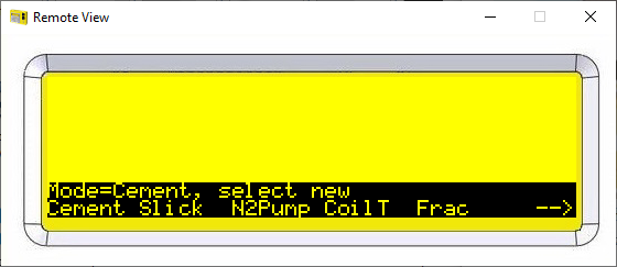
- The first step is to ensure that you have the Rapidlogger in Coiled Tubing mode. From the Rapidlogger front panel press the following keys. F6 - > F6 -> F4 -> F5 You will see the following screen:
Now press F4 to switch to Coiled Tubing mode and reset the Rapidlogger Variable.
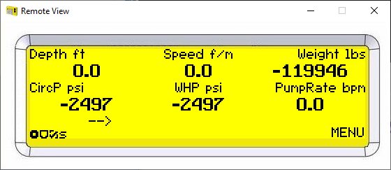
- Now power cycle the Rapidlogger by turning it off and then back on again. You should now see the following screen.
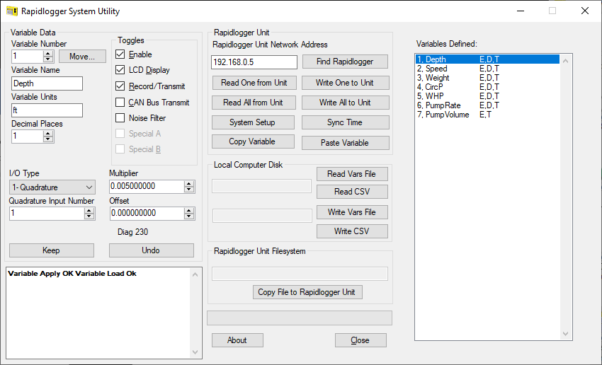
- We will now setup the calibration of each of the variables one by one. For this please use the Rapidlogger System Utility to connect to the Rapidlogger from a laptop.
- The first variable to setup is Depth. Depth is measured by a depth encoder. This encoder is connected to the Quadrature #1 input. Use I/O type Quadrature and Input number 1. The default Multiplier is 0.005. This needs to be adjusted to the proper value for your coiled tubing depth measurement wheel. Use the Rapidlogger Multiplier Calculation excel sheet to calculate the Multiplier. The calculation is on the spreadsheet tab labeled DepthEncoder. You can download the excel file from https://www.rapidlogger.com/customers/RapidloggerMultiplierCalculation.xlsx.
- The second variable to setup is speed. Speed is calculated from the Depth encoder. Use I/O type QuadratureRate and Input number 1. The Multiplier for speed is always equal to the multiplier for Depth x 60. (so if the multiplier for depth is 0.005 then the multiplier for speed would be 0.30).
- The third variable to setup for Coiled Tubing is Weight. The weight value is received from either an electronic load cell or a pressure sensor connected to the pressure line of a hydraulic load cell. In either case you need to know the CT hanging weight at 4mA and at 20mA. Enter these values in the spreadsheet on tab labeled Electric CT Load Cal to get the multiplier and offset.
- The fourth variable to program is the Circulating Pressure. If you have a 10ksi sensor then the Multiplier is 0.1907378 and offset is -2500. If you have a 15ksi sensor then the Multiplier is 0.286106661 and offset is -3750. If you have a 20ksi sensor then the Multiplier is 0.381475547 and offset is -5000. The Circulating Pressure sensor is connected to Analog Input 2.