This tech note describes the process to connect a Micro-Motion flow meter transmitter with a Rapidlogger system. The Micro-Motion has milli-ampere and frequency outputs.
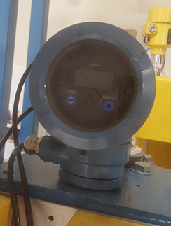
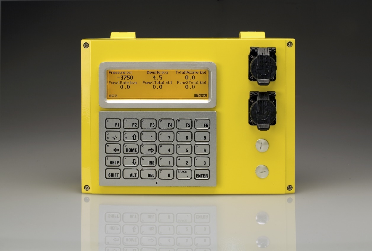
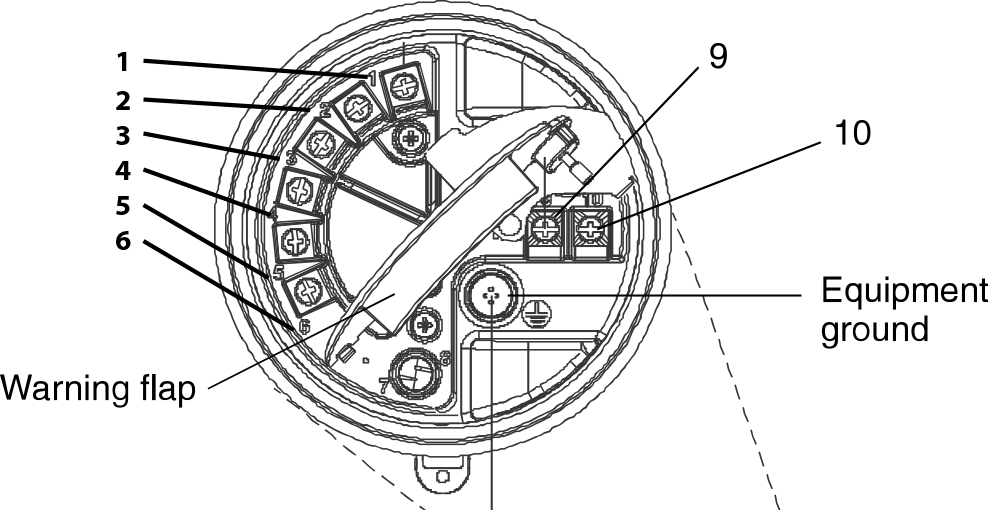
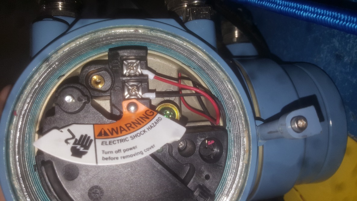
Image 1 and 2: Micro-Motion Coriolis Meter Display And Rapidlogger Unit
It is important to note that the Rapidlogger CAN NOT be used to power the densitometer, you must use a separate power source for it. Acceptable voltages are 18 to 100 VDC or 85-265 VAC.
The milliamp output on the Micromotion carry the density signal. This should be wired to the Rapidlogger mA3 input.
The flow rate output of the Micromotion unit is generally configured to be on its Frequency output. On the Micromotion, the measured variable that is assigned to the frequency output should be “Volume Flow”. The pulse/pause ratio should be setup to the default value “1:1”. The output frequency should be set to the default value of “10000Hz”. The dampening should be set to the default value of “1sec”.
If the user wants to feed the Micromotion frequency signal to the Rapidlogger. It should be wired in to the Quadrature input of the Rapidlogger. The connections should be wired as shown in table 1.
| Micromotion Terminal | Rapidlogger Terminal | |||
| 1 | mA + | TB1-14 | mA3 Input | |
| 2 | mA – | TB1-8 | DC Ground | |
| 3 | Frequency + | TB1-16 | Q1A input | |
| 4 | Frequency – | TB1-10 | DC Ground | |
| 9 | Power – | NA | NA | |
| 10 | Power + | NA | NA | |
Table 1: Micro-Motion Wired to Rapidlogger Quadrature Input