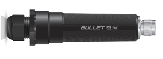
Ubiquiti BulletAC-IP67 Wireless Router Bridge Mode
This tech note describes how to setup two Ubiquiti BulletAC-IP67 Routers in bridge mode to facilitate a long distance WiFi link for a Rapidlogger System.
Equipment Needed
- BulletAC-IP67 Router 2 each
- 2 Antennas with N-Type connectors
- 2 Ethernet cords
- 2 POE adapters
- 2 24V power supply
Factory Set Passwords:
Login: admin
Password: Rapidlogger-bridge
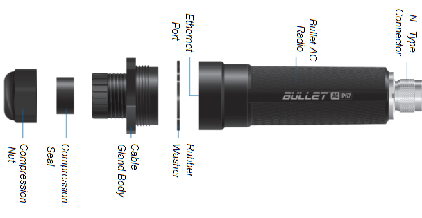
Hardware Assembly
- Unscrew the Cable Gland Body and remove it from the BulletAC.
- Unscrew the Compression Nut and push out the Compression Seal from inside of the Cable Gland Body.
- Slide the Ethernet Cable through the Compression Nut.
- Open the Compression Seal and slip it on around the Ethernet Cable.
- Run the Ethernet Cable through the Cable Gland Body.
- Connect the Ethernet Cable to the Ethernet Port on your BulletAC
- Fit the Compression Seal back into the bottom of the Cable Gland Body.
- Screw the Compression Nut to the Cable Gland Body.
- Tightly Screw the Cable Gland Body to the BulletAC Radio.
- Connect the BulletAC to the N-Type connector of your antenna.
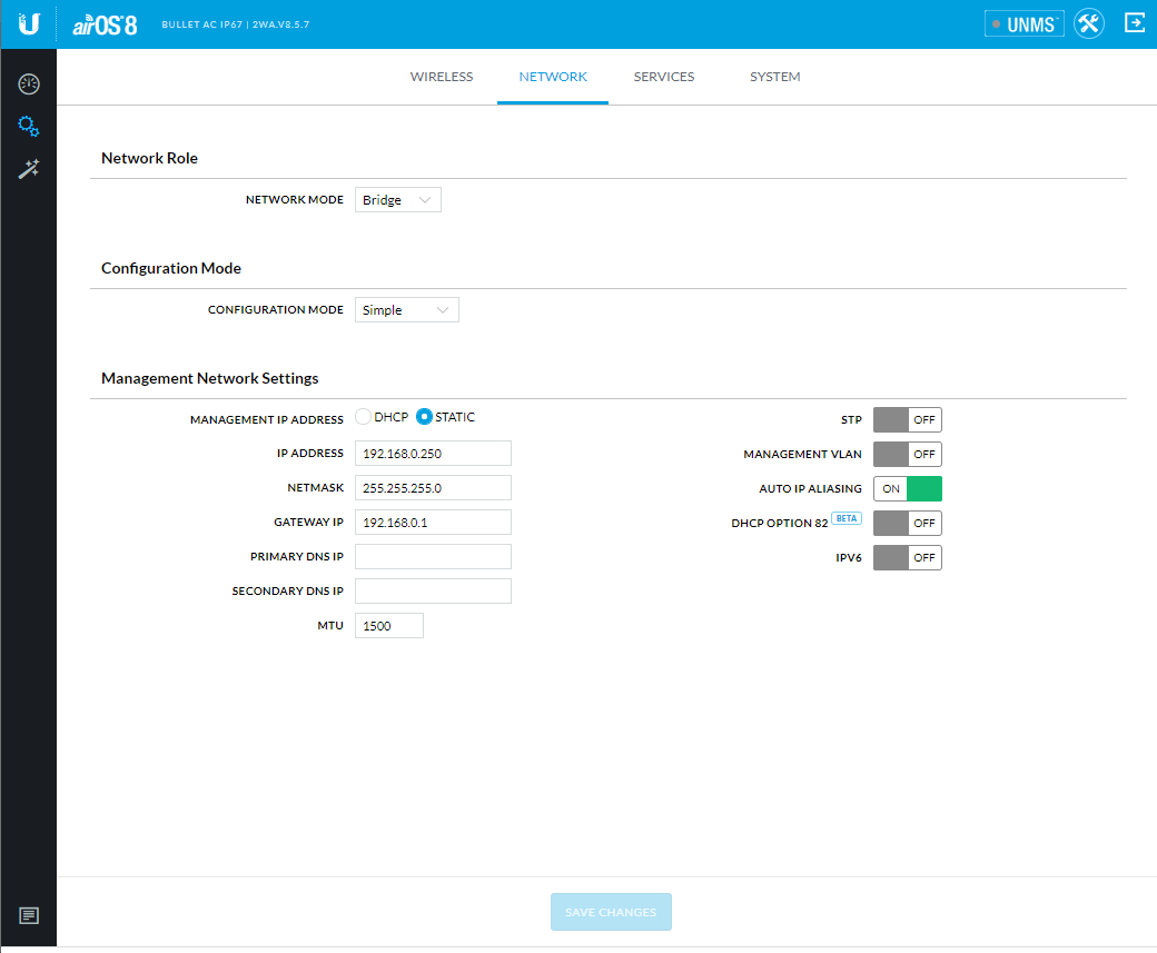
Connecting Through Web Portal
- Connect to your Bullet AC through Wi-Fi using the SSID named: BulletAC-IP67:<MAC Address>
- The MAC Address can be found on the bottom of the shipping box with a (G) before it.
- The MAC Address can also be found on the bottom of the BulletAC under the Ethernet Port.
- Launch a web browser and go to the URL http://setup.ui.com
- Select your Country and Language, agree to the Terms of Use and click Continue.
- Create a Username and Password, confirm by pressing Save.
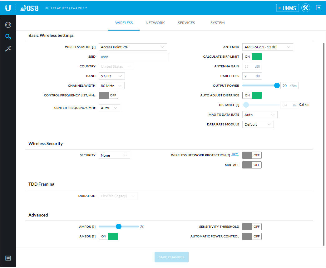
- In the Wireless section, choose your antenna.
- Change settings to your preferences and press the Save Changes button at the bottom of the screen.
- In a bridge configuration one of the two devices needs to be configured as an access point (AP PtP) and one device has to be configured as a Station (Station PtP)
- For the device being setup as access point upload the Setup File called “AccessPntSetupRapidloggerBridge.cfg”
- For the device being setup as station upload the Setup File called “StationSetupRapidloggerBridge.cfg”
- The menu option to upload setup file is under Settings->System->Upload Configuration
- Alternately all of the settings can also be performed from the Android APP from Ubiquiti called UNMS
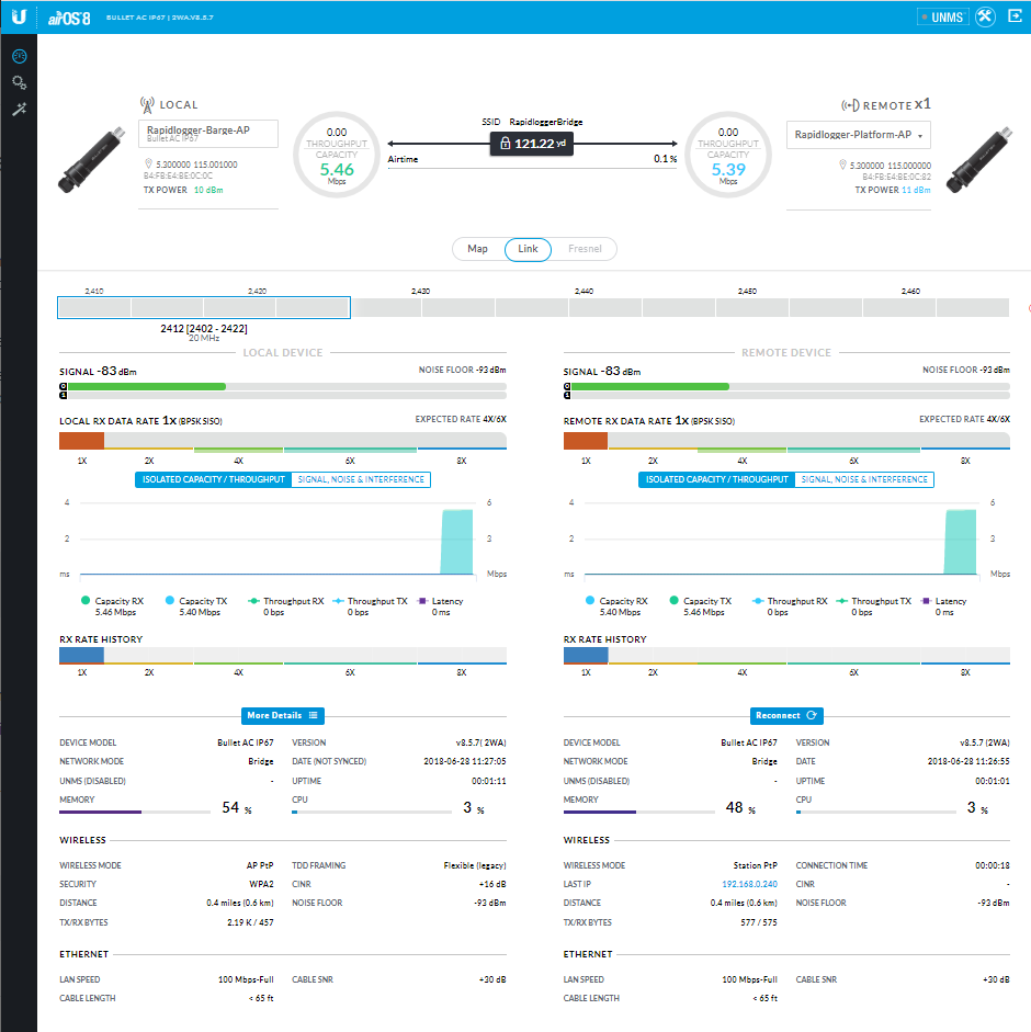
Testing
1. Once configuration is completed, connect the cables to a Rapid logger system.