This tech note describes how to wire a CT unit to shut-down when an overpull condition is detected by the Rapidlogger System.
The First Step is to procure an appropriate hydraulic solenoid valve for dumping the injector hydraulic pressure to tank. A suggested valve for this purpose can be (Hydraforce SV08-33-6TN24DG).
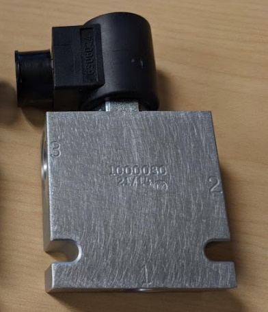
This is a 3Way 2 position, 3ksi 3 GPM valve with a 24VDC coil.
This document only describes a non-failsafe installation. The valve should be installed in the hydraulic circuit such that when it is not energized it allows (and not interrupts) the pilot hydraulic pressure flow to go from the main supply pressure to the injector motor pressure control knob/valve on the control console. In this installation if the OPSV system is not powered up or not functioning then the CT unit will continue operating as normal. It is only when the Rapidlogger OPSV senses an over pull condition it will energize the hydraulic valve and dump the priority pilot pressure to the tank and stop the CT unit. The exact hydraulic circuit will vary from CT unit from different manufacturers.
After this hydraulic hookup is completed then the hydraulic setup should be tested by actuating the valve and checking if the CT unit stops and sets the injector brakes. In order to test the valve connect two of the terminal to 24VDC+ and 24VDC-. The terminals are shown below.
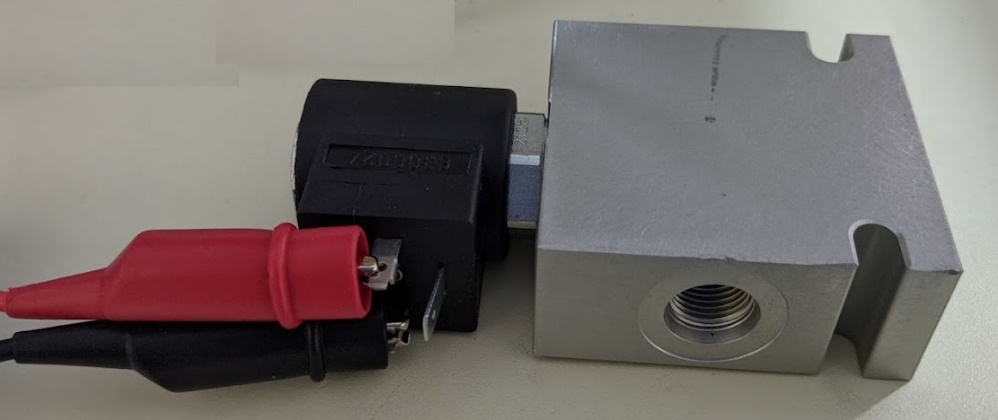
Actuating the valve requires 24VDC and about ½ ampere current.
The next step is to connect the electrical contacts of the valve to the Rapidlogger unit. The connection should be made as follows.
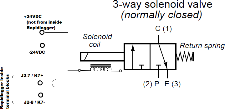
Be sure to not source the +24VDC power for the solenoid valve from inside the Rapidlogger box as this will cause power loss and reset the unit. Source the +24VDC and GND from a separate connection/cable from within the Rapidlogger power-supply.
ow test the operation of the valve by powering up the Rapidlogger and actuating the valve from the diagnostic screen on the front panel.
Use Menu option F6->F6->F5->F2->F4.
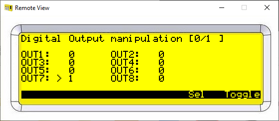
Now press F5 until the OUT7 / Relay 7 is highlighted. Pressing F6 now will toggle the valve on and off. When the valve toggles on the K7 relay LED on the main board should toggle on and off.
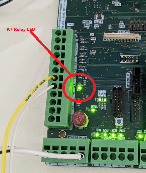
If you do not hear the valve toggling on and off then either the wiring is not correct or the power supply voltage and current are not sufficient.
Software Setup
The next step is software setup of the unit.
Firmware Requirement
The minimum firmware required for best results with the over pressure shutdown is version 9.9K or newer. Download the latest version from our website. It is available in the Support and Downloads section.
RapidVu Software Requirement
The minimum version of RapidVu software that should be used is firmware required for best results with the over pressure shutdown is version 4.65 or newer.
Setup Software Requirement
The minimum version of Rapidlogger Utility software that should be used is version 4.20.0.
Variable Setup
Check the firmware version on the Rapidlogger. It is displayed on the initial screen when you first power up. OR you can see it on the RapidVu software screen.
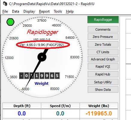
If the firmware version is not 9.9K or higher then update the firmware. Check the software version if it is not at least 4.65 then update it.
The first step is to save all your variable setups using the Rapidlogger System Utility. If you do not know how to do this then refer to tech note 13. Or you can write down the multipliers and offsets of the Depth, Speed, Weight, Pump Rate and Pump Volume variables.
The next step is to reset the Rapidlogger again to Coiled Tubing Mode. You can do this by pressing F6 - > F6 -> F4 -> F5 -> F4 - > ENTER.
This will put the Rapidlogger in CT Mode and reset all system variables to factory defaults. Now restore the values of the Multipliers and offsets of the Depth Speed Weight and Pump variables from your previous notes.
When you now look at the Rapidlogger System variables with the utility software you should see something like the following.
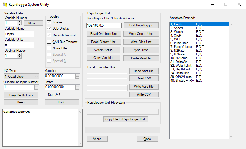
Note that variable 40 has been connected to the shutdown relay. Limit values for Weight Depth and Delta-Weight have been set.
Rapidlogger setup is complete.
Now when the CT weight exceeds the shutdown weight the Relay will be tripped and the solenoid valve will shut-down the unit.
When the unit trips on overpull, or depth etc the following message appears on the screen.
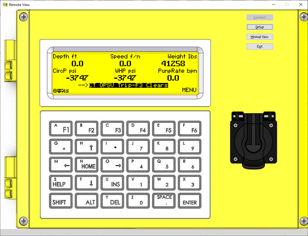
Pressing F3 clears the shutdown latch. Once everything is setup and running the user can easily set the Overpull Trip limits from the RapidVu program during the job.
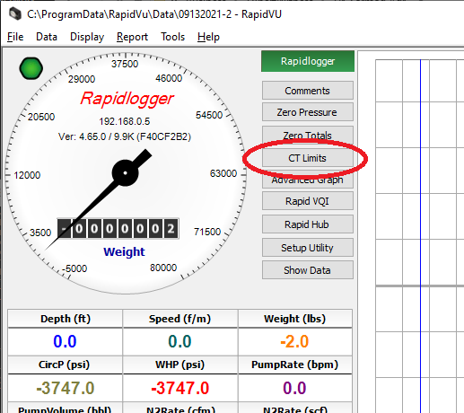
If you press the “CT Limits” button the following dialog box appear and it allows the user to set the values of the over-pull trip limits for that job only.
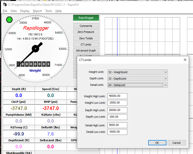
If a permanent change to the overpull limits is desired then the user needs to use the Rapidlogger Utility Software to make the change.
