Calibrating the Rapidlogger Depth Encoder
This tech note describes how to use the Rapidlogger System Utility OR the Rapidlogger Block position utility to calibrate depth OR block position.
- The first step is to ensure that the depth encoder is correctly wired to the Rapidlogger.
- Now switch on the Rapidlogger Unit.
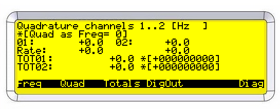
- Once the unit is powered up change to the depth encoder quadrature diagnostic screen from the front panel. You can do that by pressing F6, F6, F5, F2, F2.
- The following screen will appear on the Rapidlogger LCD panel .
- Once you are on this screen turn the encoder shaft clockwise. The number for the values on the LCD screen should increase. And with you rotate the encoder shaft anti-clockwise the number for the quadrature values on the LCD screen should decrease. This means that power is going to the encoder, the encoder is working and the wiring to the Rapidlogger is correct.
- Now if you are calibrating depth on a Drilling or Workover Unit with a draw-works winch and travelling block etc go directly to STEP 18.
USING the Rapidlogger System Utility to Calibrate Depth for CT and Slickline
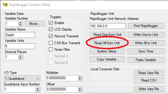
- The first step is to start the Rapidlogger System Utility on a laptop computer connected to the Rapidlogger Unit over ethernet.
- The second step is to click on “Read All from Unit” button
- This will load the contents of the setup from the Rapidlogger System memory to the laptop.
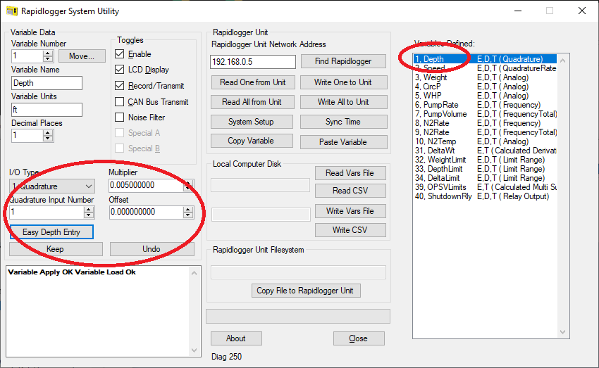
- Now press click on the Depth variable on the right so you can see its settings in the setup area on the left.
- You will now see the Multiplier and Offset for the Depth Encoder Variable on the screen.
- If this is the first time you are calibrating depth you should click on the “Easy Depth Entry” button.
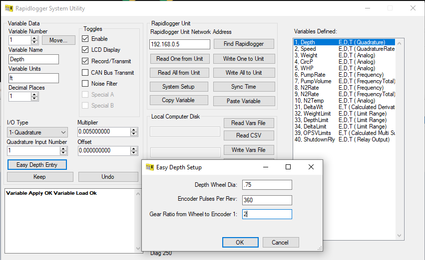
- You can enter the depth wheel diameter. For Coiled Tubing this means the diameter of the friction wheel on Injector or Reel. For Slickline this means the diameter of the pinch roller on the slickline unit.
- The value of Encoder pulses per Rev depends on the encoder you have purchased. These are usually listed on the label on the side of the encoder.
- The friction wheel (on a CT unit) or the pinch roller (on a slickline unit) are usually connected with a gear to the encoder. The gear ratio would need to be written in the dialog box. If the gear ratio is 2.7:1 then write 2.7 in this box.
- Click OK and then press “Write One to Unit” and the settings will be saved to the Rapidlogger Unit.
- The Multiplier for speed is 60 times the Multiplier for Depth. This is because speed is usually measured in feet per minute and there are 60 seconds in a minute.
USING the Block position utility to calibrate depth on the Drilling Rig draw-works winch
- The first step is to start the Rapidlogger Block Position on a laptop computer connected to the Rapidlogger Unit over ethernet.
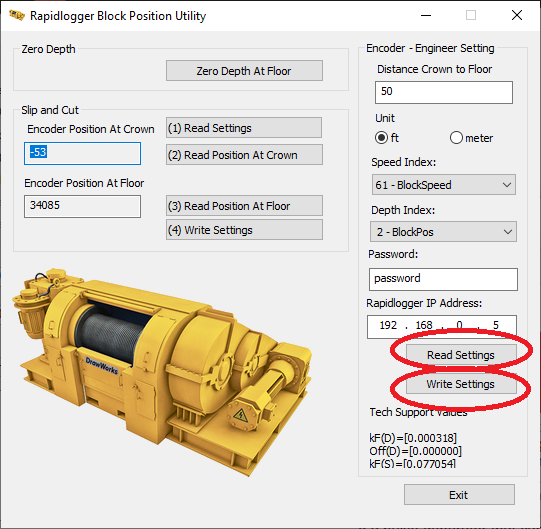
- The second step is to click on the password field and enter “password” as the password. This simple password is in place to prevent users from accidently changing important block position / winch encoder settings on the unit.
- After entering the password click on “Read Settings”. Variable setting will be loaded from the Rapidlogger.
- Here you only need to change the “Distance Crown to Floor” to match you exact Rig crown height. This value needs to be exact to a fraction of an inch since this is used to calibrate the depth encoder. The Crown is highest possible position and the Floor is the lowest possible position for the travelling block. If these are not already physically marked on your rig then they please mark them in a permanent manner. These positions will be needed again later in the calibration and also in the day to day operation to “slip and cut” the winch wire rope.
- Now exit the Block position utility.
- Start the block position utility. But do not enter the password this time.
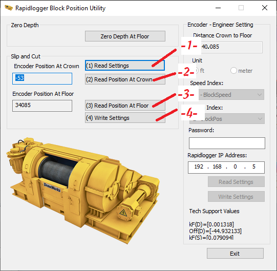
- Click on button marked “1”. This will read the setup from the Rapidlogger Unit memory.
- Now ask the driller to operate the draw-works winch to move the travelling block to the crown position (highest possible position for the travelling block).
- Click on button marked “2”. This will save the crown position value temporarily.
- Click on button marked “3”. This will make the system wait for the driller to move the travelling block to the floor position (lowest possible position for the travelling block).
- Ask the driller to operate the draw-works winch and move the travelling block to the floor position.
- Click on button marked “4” (Write Settings). This will save the crown and floor positions in the Rapidlogger System memory.
- Initial calibration is now complete.
- Now every time you need to remove a section of wire rope from the winch you need to repeat the steps 23 to 30.