This tech note describes how to connect two Rapidlogger units in a Master Slave configuration. Some uses of this configuration include Rapidlogger ExD injector slave unit and Rapidlogger multi-pump master slave configurations.
The first step is to make the electrical connection between the two units.
Electrical Connection between master and slave
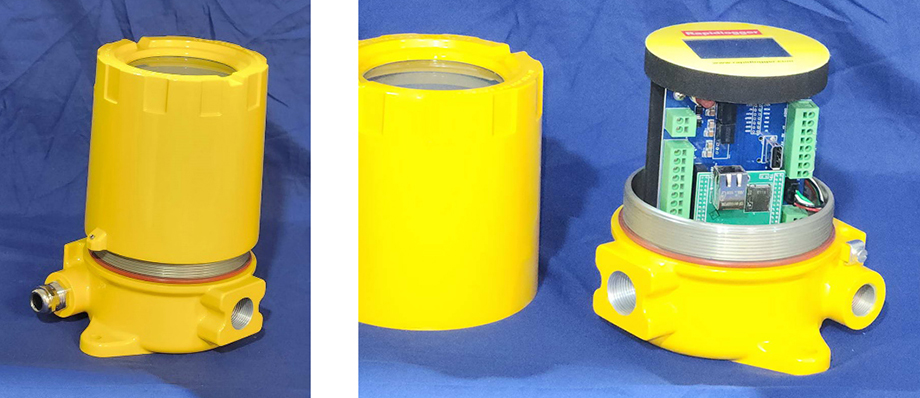
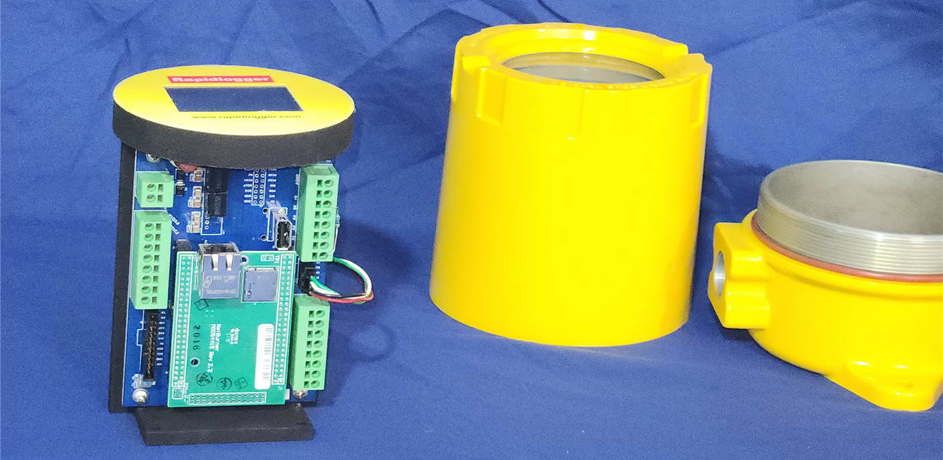
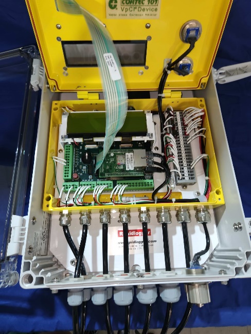
- Unscrew the cover for the Rapidlogger ExD.
- Now undo the screws on the bottom of the plastic mounting frame and remove it from the base.
- Normally a four-conductor cable is used to connect the master and slave. The two conductors used for connecting the CAN signals must be a twisted pair. The power conductors can be straight or twisted pair.
- In some configurations power and CAN signals can come on two different cables. This is the case when DC 24V power is available on the injector or pump where the Rapidlogger ExD is to be installed.
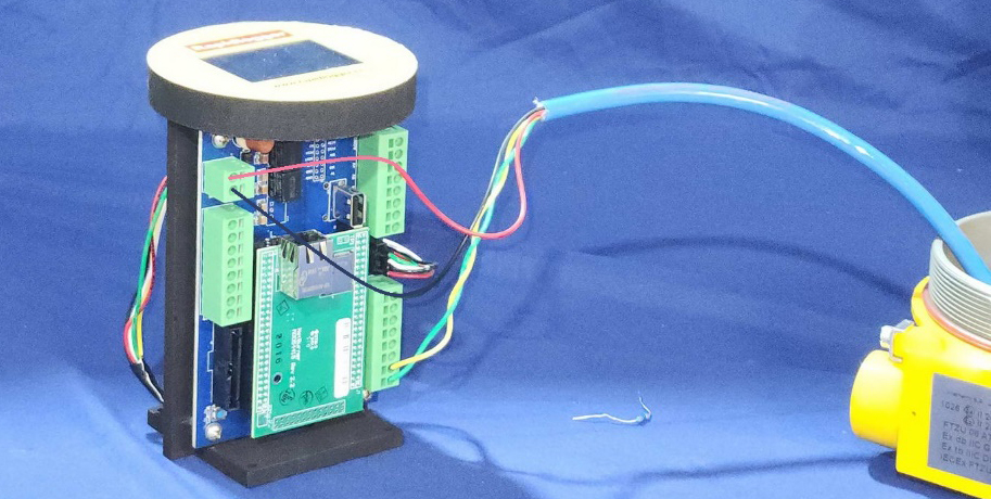
- Thread the power/signal cable through the ExD cord grip and strip the ends of the conductors. Now insert the wires into the following terminal.
A) Red wire - J1-1
B) Black wire - J1-2
C) Green wire - J3-1
D) Yellow wire - J3-2
- In the standard Rapidlogger supplied Master/Slave Cable (part number 00-92595, VAR-813) the green and yellow conductors are twisted pair while the red and black conductors are not.
- The next step is to connect the other end of the cable to the Rapidlogger Master
- Do note that Master/Slave cable is not armored and needs to be routed safely in the hazardous area. This means that the cable must be run in a manner that does not allow it to be shorted or crushed in the hazardous area. Route this cable in a cable-tray or a protected wire bundle.
- Route the other end of the master/slave cable to the Rapidlogger Master Unit.
- Thread the cable through the cord-grip and into the Rapidlogger Main unit.
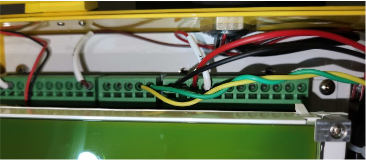
- Strip the wires and insert them into the correct terminals as shown below.
A) Red wire - - J1-2
B) Black wire - J1-5
C) Green wire - J8-1
D) Yellow wire - J8-2
- The wiring is now complete. The next step is to set up the software configuration of the Master and Slave units to enable the CANbus operation and select the variables.
- Depending on the cable length and the number of master/slave devices on the CANbus, termination resistors (120ohm) may be needed on one or both ends of the cable.
Software and variable configuration
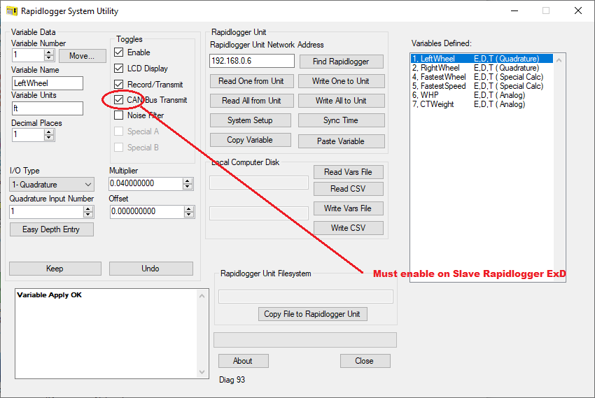
- Configure the Slave unit first. Use the Rapidlogger Setup utility to configure the required variables and CAN bus settings. The laptop ethernet cable must be connected to the Rapidlogger ExD slave unit.
- For example, if you are setting up the Rapidlogger ExD for a CT Injector unit then you are probably going to install one or two depth encoders in to the unit. Additionally, WHP may also be routed in to the Rapidlogger ExD, or you may choose to route the CT Injector head weight loadcell here. All of these are options that may or may not be used depending on your specific requirements.
- Each one of the variables on the slave unit that are needed to be seen on the Master unit over CANbus must have the “CAN Bus Transmit” checkbox checked.
- This finishes the setup of the CT injector variables
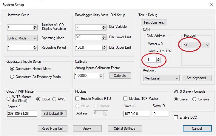
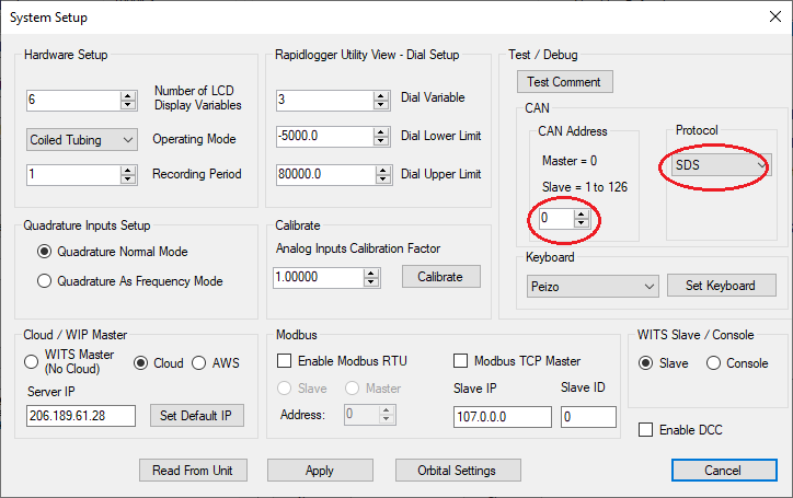
- The next step is to configure the CANbus settings. Use the system setup menu to configure the CANbus on the Rapidlogger ExD. The CAN address should be selected as ‘1’ and the CANbus protocol as ‘SDS’.
- Use “Apply” to save the settings and power cycle the Rapidlogger ExD. The setup of the Rapidlogger slave is complete.
- Start the configuration of the Rapidlogger Master unit. The laptop ethernet cable must be connected to the Master Rapidlogger for this setup,
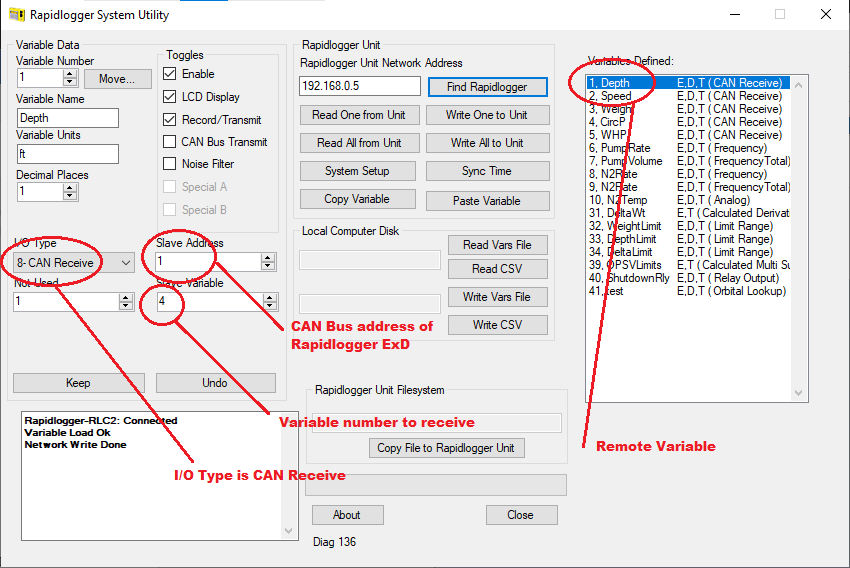
- If the need is to configure the variable “Depth” to come from the Slave Rapidlogger ExD then change its I/O type to “CAN Receive”. The Slave address should be changed to “1” and the slave variable to “4”. This completes the variable setup.
- The next step is to configure the CANbus on the Rapidlogger Master unit.
- Use the system setup dialog to make these configuration changes.
- The CAN bus address must be set to “0” on the master unit and protocol set to “SDS”. Use “Apply’ to save the settings to Rapidlogger unit.
- Power cycle the Rapidlogger Master unit. The software configuration is now complete.
- You can verify the proper CAN bus communication on the Rapidlogger Master unit “CAN Diagnostics” screen.
- To access the CAN diagnostic screen press F6 -> F6 -> F5 -> F3 -> F2
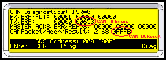
- The following diagnostic screen will appear on the Rapidlogger LCD display.
- If the CAN Bus connection is good and communication is taking place correctly then the “Received Packet” count should continue increasing. And the “Transmit Error” count should not increase.
- However, if the CANbus connection is not good or there is a software configuration issue then the “CAN TX Errors” field will increase, and the “CAN TX Result” will have a value such as FFFB.
- If this is the case, then double check your settings and connection configuration.
USING the Rapidlogger System Utility to Calibrate Depth for CT on the Rapidlogger ExD slave unit
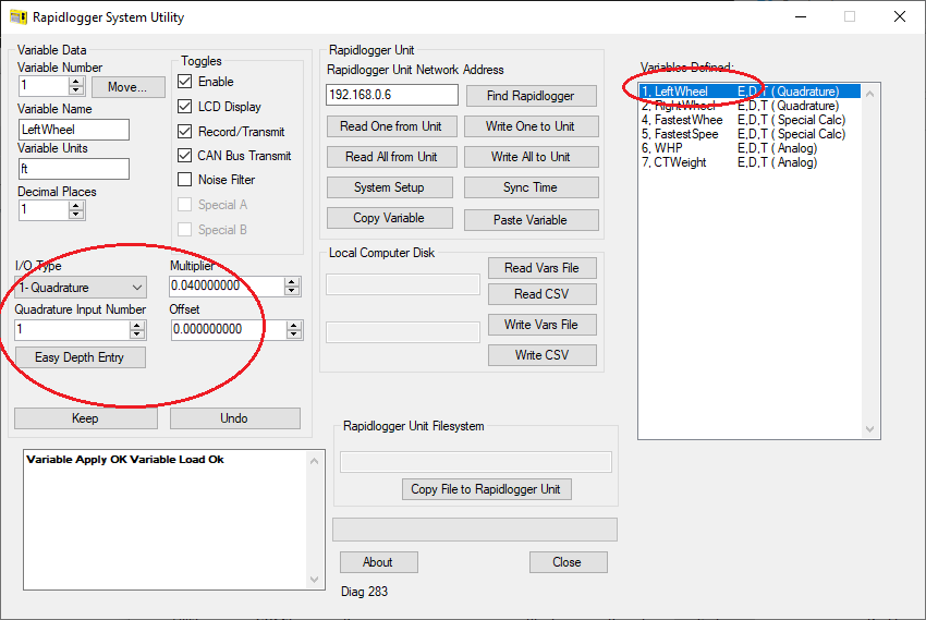
- The first step is to start the Rapidlogger System Utility on a laptop computer connected to the Rapidlogger ExD slave Unit over ethernet.
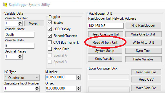
- The second step is to click on “Read All from Unit” button
- This will load the contents of the setup from the Rapidlogger System memory to the laptop.
- Now press click on the Depth variable or Left/Right Wheel Depth variable on the right so you can see its settings in the setup area on the left.
- You will now see the Multiplier and Offset for the Depth Encoder Variable on the screen.
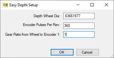
- If this is the first time you are calibrating depth you should click on the “Easy Depth Entry” button.
- Enter the 3 settings in the Easy Depth Setup dialog box.
- For example, if the wheel circumference is 2 feet then its diameter is 0.663661977 ft. and that should be entered. The number of encoder pulses per revolution is normally listed on the depth encoder and it should be entered in the second field. If there is not gear ratio between the Encoder and the depth friction wheel then enter the number 1. Otherwise enter the value of the gear ratio.
- Click OK and then press “Write One to Unit” and the settings will be saved to the Rapidlogger Unit.
- The Multiplier for speed is 60 times the Multiplier for Depth. This is because speed is usually measured in feet per minute and there are 60 seconds in a minute.
- Enter the correct Multiplier for speed in the variable for the CT speed.
- The configuration and setup are now complete.