10700 Corporate Drive, Suite 108 Stafford, Texas 77477
Support – Tech Note 44
Replacing a CPU Module in a Rapidlogger System
This tech note describes the process to replace the cpu module in the Rapidlogger systems. Panels equipped ST10F269 or C167CS CPUs can have the CPU replace this way.
The most likely reason to replace the CPU module is that you have received a new CPU module with updated firmware.
The first step in this process is to back up the system settings and variables in the unit. This can be done by following Tech Note 13.
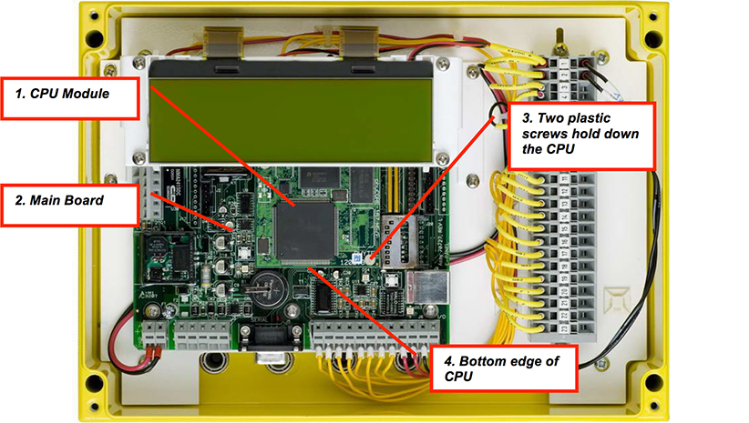
Figure 1
Turn off the Rapidlogger System.
Remove all power and signal cables from the unit.
Take the unit in to your electronics workshop and place it on a bench.
Place the Rapidlogger on a horizontal surface.
Open the yellow metal lid and leave it hinged up.
Before touching anything inside the box make sure that your hands are clean.
Make sure that there is no static electricity present on your hands. You can do this by putting on a grounded antistatic wrist strap or touching a grounded piece of metal.
Identify the Main board and the CPU module inside the Rapidlogger using Figure 1 as a reference.
Use a small screw driver to remove the two plastic screws that hold the CPU module down. Place these carefully to one side.
Note the orientation of the CPU module on the main board.
Put one finger tip under the bottom edge of the CPU Module and gently pull the CPU module away from the main board.
The CPU module should lift away from the main board completely.
Now take the new CPU module and rotate it so that the orientation of the module is the same as that shown in the Figure 1.
Align it on the connectors on the main board.
Press down on the CPU module with very gentle pressure alternately on the top edge and the bottom edge.
If the CPU was aligned with the connectors properly it will easily seat back.
If not then lift up the CPU and try again from step 13.
Once the CPU is seated completely in the connector then install the two plastic screws.
Close the lid to the Rapidlogger system and connect it back to its power supply.
It should power up normally.
The final step in the process is to restore the system settings and variables in the unit. This can be done by following Tech Note 43.