This tech note describes how to wire a pumping unit to shut-down when an overpressure condition is detected by the Rapidlogger System.
The First Step is to determine the type of shut-down mechanism in place on the pumping unit that will be used to shut-down the pump unit.
For shutting down the pump unit via engine stop most diesel engines have a shutdown solenoid. When this is activated the engine on the pump unit shuts down.
In order to shutdown the pump during an overpressure condition the Rapidlogger System utilizes a relay output. The software in the Rapidlogger Monitors the Pump Pressure, if this pressure exceeds the Overpressure limit then the Relay is triggered.
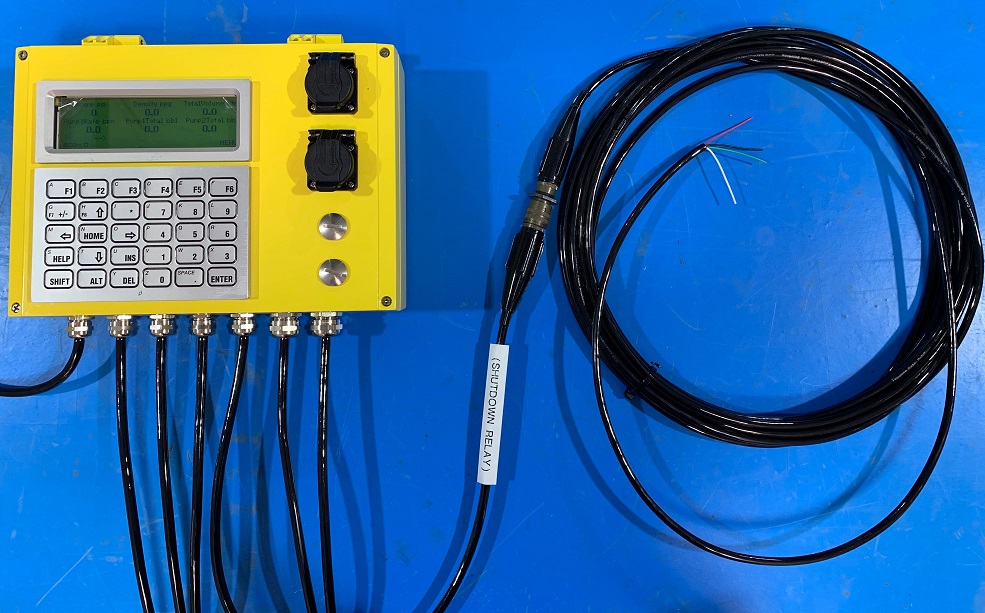
The picture above shows the outside of the Rapidlogger with the shutdown / Auxiliary cable connection.
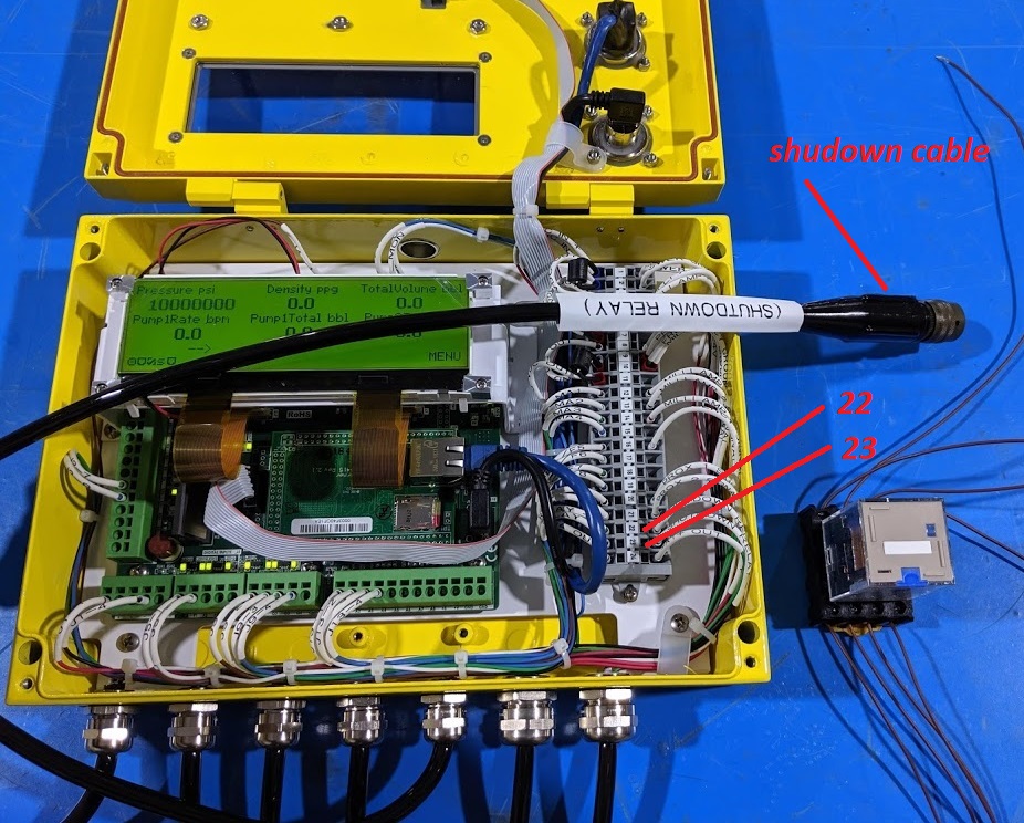
The picture above shows the inside terminal block of the Rapidlogger. In a standard Rapidlogger the terminals 22, 23 are the relay output terminals. They are generally wired to an external cable marked Shutdown Relay or Over-Pressure, or Auxiliary cable or Signal cable.
The signal would be on external connector pins C and D or wires color Blue (Positive) and Brown (Negative) on the cable.
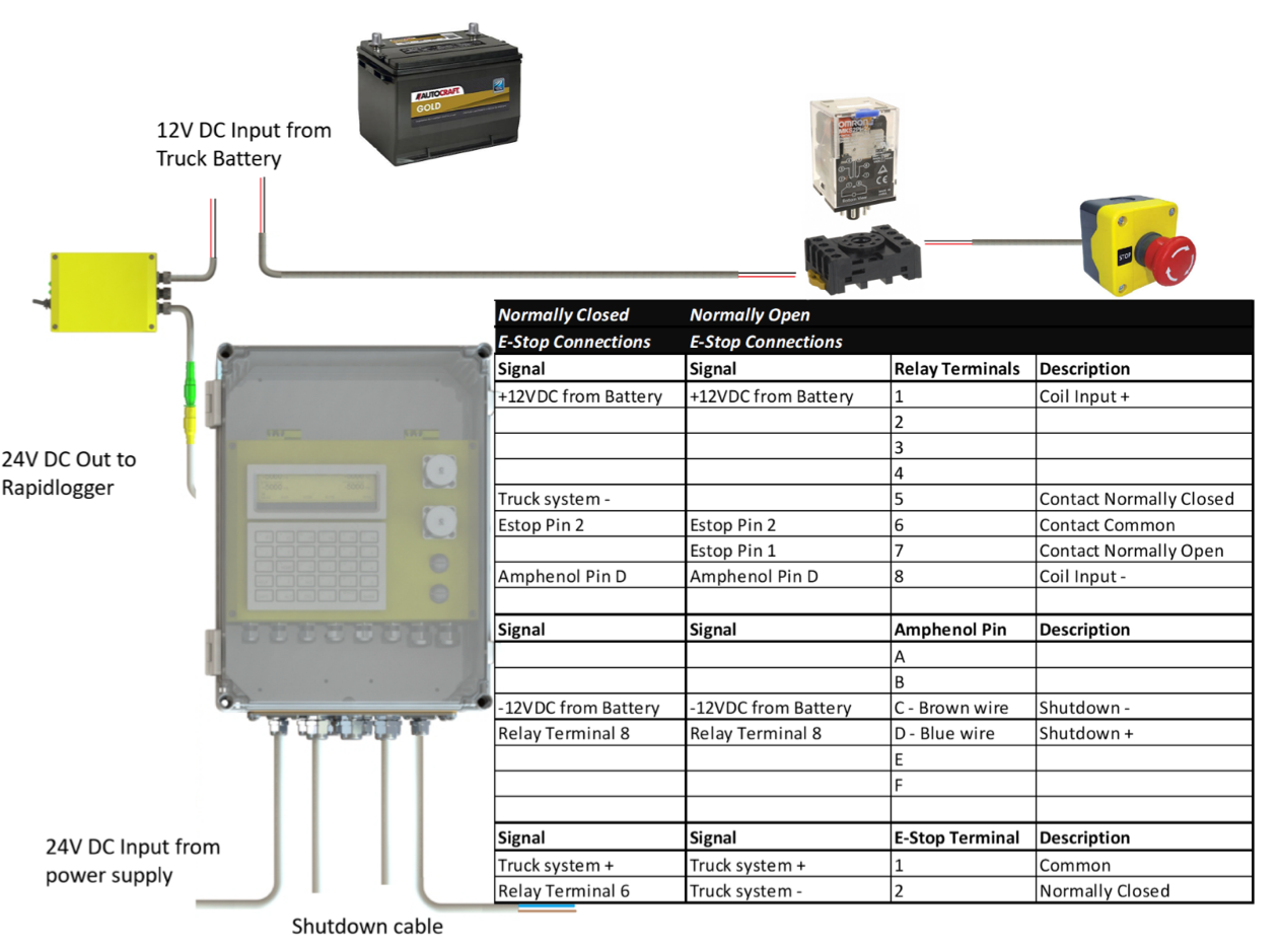
The Second Step is to connect the Rapidlogger Shutdown output to a shutdown solenoid. This can be wired directly to the shutdown solenoid, or through an isolation relay. Using an isolation relay is the preferred method, since this allows Engine and Rapidlogger to operate from different power supplies. This also allows the use of normally open or normally closes E-Stop switches to be used.
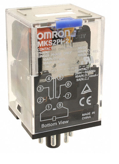
The picture above shows a typical isolation relay used the part number of this particular one is Omron (MKS2PI-2 DC12); However any similar relay can be used. The relay socket shown in this image is Omron (PF083A-E).
Connecting without an Isolation Relay
Connect the pump units 12 or 24 VDC power supply positive to the positive terminal of the unit’s shutdown solenoid. Connect the other terminal of the solenoid to the Blue wire of the shutdown cable (Amphenol connector pin D, or Rapidlogger internal terminal JB1-22). Connect the Brown wire of the shutdown cable (Amphenol connector pin C, or Rapidlogger internal terminal JB1-23) to the ground of the pump unit’s 12 or 24VDC power supply. Wiring is complete. Every time the overpressure will trigger the Rapidlogger will activate the shutdown solenoid.
Connecting to Shutdown Solenoid with an Isolation Relay
This is a DC coil relay and the coil is on terminal 1 and 8. Connect the pump unit’s 12 VDC power supply positive to terminal 1 of the isolation relay. Connect the terminal 8 of the solenoid to the Blue wire of the shutdown cable (Amphenol connector pin D, or Rapidlogger internal terminal JB1-22). Connect the Brown wire of the shutdown cable (Amphenol connector pin C, or Rapidlogger internal terminal JB1-23) to the ground of the pump unit’s 12 VDC power supply. Every time the overpressure will trigger the Rapidlogger will activate the coil of this relay. Now connect terminal 6 of the isolation relay to the positive terminal of shutdown solenoid. The negative terminal of the shutdown solenoid should be connected to terminal 7 of the relay. Leave any wires that were running to the solenoid before as is and do not disconnect them.
Connecting to E-Stop Switch with an Isolation Relay
This is a DC coil relay and the coil is on terminal 1 and 8. Connect the pump unit’s 12 VDC power supply positive to terminal 1 of the isolation relay. Connect the terminal 8 of the solenoid to the Blue wire of the shutdown cable (Amphenol connector pin D, or Rapidlogger internal terminal JB1-22). Connect the Brown wire of the shutdown cable (Amphenol connector pin C, or Rapidlogger internal terminal JB1-23) to the ground of the pump unit’s 12 VDC power supply. Every time the overpressure will trigger the Rapidlogger will activate the coil of this relay.
Now if the emergency switch being used is of a normally open type connect terminal 6 of the isolation relay one terminal of the E-Stop, and wire the terminal 7 (Normally Open terminal) of the relay to the other terminal of the E-stop. Leave any wires that were running to the E-Stop as before as is and do not disconnect them. The relay will be in parallel with the E-Stop.
However, if the emergency switch being used is of a normally closed type connect terminal 6 of the isolation relay one terminal of the E-Stop, and wire the terminal 5 (normally closed terminal) of the relay to the wires that were originally connected to that terminal of E-stop. The relay will be in series with the E-Stop.
Firmware Requirement
The minimum firmware required for best results with the over pressure shutdown is version 9.7a or newer. Download the latest version from our website under Support and Download.
RapidVu Software Requirement
The minimum version of RapidVu software that should be used is firmware required for best results with the over pressure shutdown is version 4.24.1 or newer.
Setup Software Requirement
The minimum version of Rapidlogger Utility software that should be used is version 4.8.8.
Variable Setup
If only one pump needs to be shutdown then only one shutdown variable needs to be setup. The following example shows Variable 11 being setup as Shutdown. The IO type selected is “Relay Output”. We select relay 7 since this is the Relay we wired to the shutdown solenoid in the earlier part of this document.
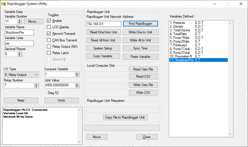
We need to Check the Relay Latch Check box since we want the pump unit to remain in shutdown condition until we clear the over pressure. Now enter Variable 1 as the compare variable since this is the pump pressure. Enter the shutdown pressure in the Limit Value field here we have entered 4900 psi. Now press the Write One to Unit button. Restart the Rapidlogger.
Once the Rapidlogger System Senses Pressure above 4900. It will trigger the shutdown Relay and Latch it. Once the pressure has gone down below 4900 psi you can press F3 to clear the shutdown latch. And allow the unit to be started again.
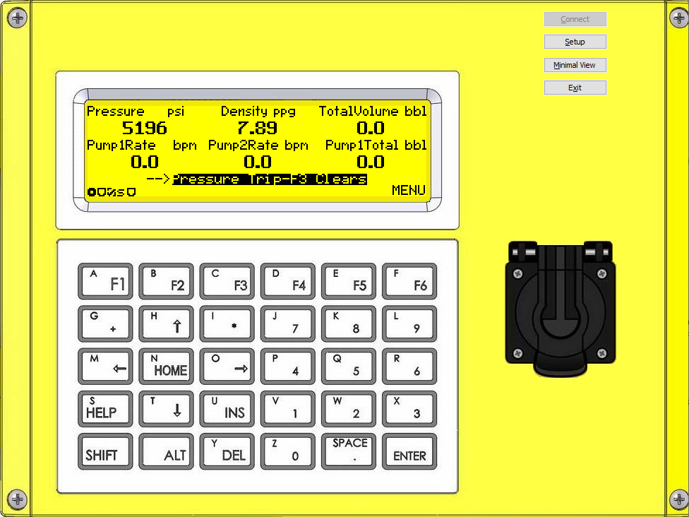
Another way to clear the latch is to click on the shutdown pressure button on RapidVu program.
