This tech note describes the process to program a software latching relay in the Rapidlogger System.
This function is only available on the Nextgen Rapidlogger. The minimum firmware version required for this functionality is 9.0d. Rapidlogger Utility Version 4.2.0.0 is also needed to set this up.
This is advanced functionality implemented for specific customers. Only advanced users are advised to utilize this functionality.
Variable Setup:
The two variables setup for this functionality are one Relay variable and one latch release variable.
When using the latching functionality ONLY ONE RELAY can be programmed.
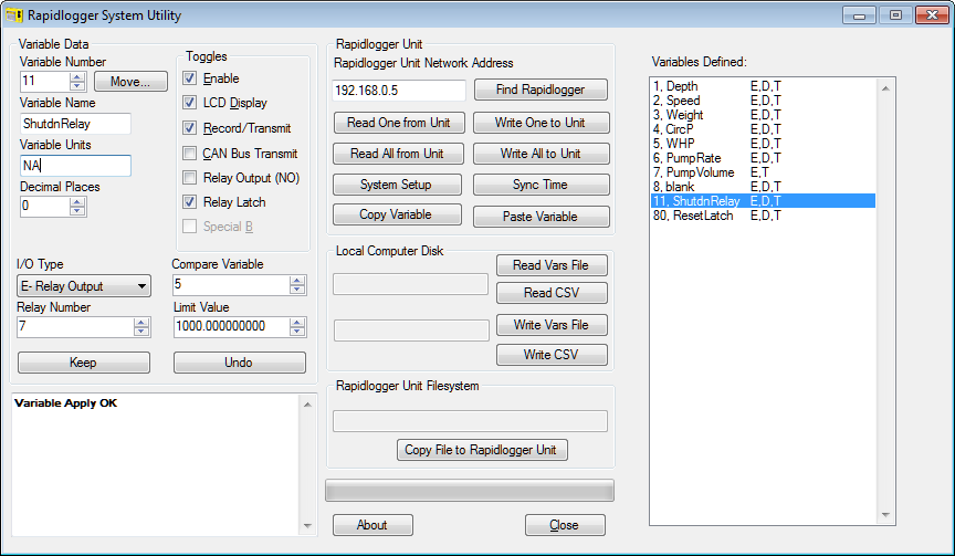
Setting up the Relay Variable:
Check the Relay Latch Check box if you want to use latching functionality. Note that any Relay number can be used as long as only one relay is programmed in the entire setup file. The Relay can be used in NO or NC mode. Any variable number can be used to store this Relay setup.
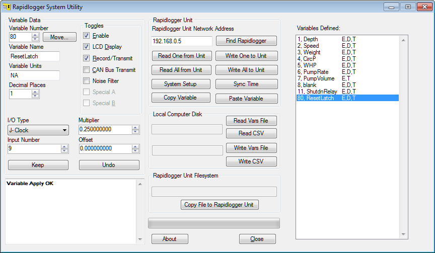
Setting up the Latch Release Variable:
Only variable 80 can used as the Latch release function. When the value of this variable goes below 1, the latch is released. So if this function is not programmed then the latch will never latch. The above example shows an internal clock being used as the data source for this variable. The internal clock ticks at 1 second intervals. The multiplier 0.25 shown in this variable simply slows the unlatching of the Relay to be around 2-3 seconds.
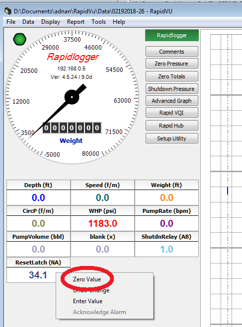
Once the relay is triggered the state is latched. In order to reset the relay the user would have to left click on the ResetLatch Variable in RapidVu and click on Zero Value.
Another way to program the ResetLatch variable would be to tie it to an analog input. Then that particular analog input could be pulled high or low with an externally wired push button (do not exceed 5V DC on the analog input). When the push button is pressed the input could be brought to low voltage and the latch could be reset.
