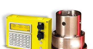
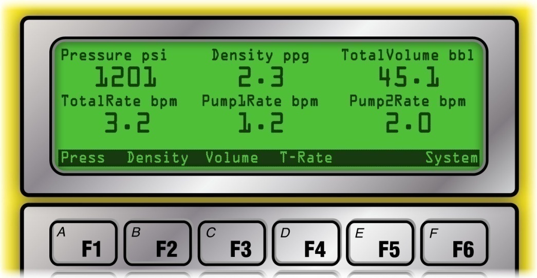
When the Rapidlogger unit is operated in the cementing mode, all of the on screen menu options are specifically configured for cementing operations. Pump pressure, density, total volume, total rate, pump rate 1, and pump rate 2 are the parameters that are displayed on the screen. The screen can be configured to show either all six of these parameters or only the first four. While the system only shows up to 6 parameters on the LCD panel, many more parameters can be recorded to the SD memory card and transmitted to the PC over the network.
Once powered on the Rapidlogger starts displaying and recording data automatically. The user can access the cementing menus by pressing F6. When F6 is pressed the following menu appears on the screen and the user can edit settings for pressure, density, total volume, and rate.
Pump Pressure
Pump pressure is the first parameter displayed on the Rapidlogger screen. The pump pressure on a cementing unit is generally measured with a pressure transducer in the main treating line. In order to edit the pressure readings press F6 and then F1 from the main screen and the following menu will appear
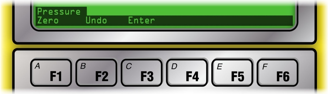
Now press F1 to zero out the pressure. This option is used to clear out a small pressure offset from the variable when it is known that the pressure should be zero or atmospheric. In order to clear out the pressure offset or undo the zeroing of the pressure variable press F2. If the actual pressure is known such as due to a calibration or dead weight test or from a calibrated client pressure gage, and the Rapidlogger reading needs to match that calibrated reading, press F3 and the system will allow you to enter a new pressure value. Powering the system off and then on again will clear out this pressure offset value.
Slurry Density
The cement slurry density is the second parameter displayed on the Rapidlogger screen. The density is measured by means of a densitometer installed on the treating line. In order to edit the slurry density readings press F6 and then F2 from the main screen and the following menu will appear
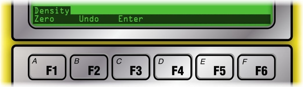
Now press F1 to zero out the density. This option is used to clear out any small offset in the density value variable when it is known that the density should be zero. In order to clear out the density offset or eliminate the zeroing process press F2. If the actual density is known, such as due to a calibration with pure water or from a calibrated client densitometer, press F3 and then you can enter a new density value which will be stored in the system only for that particular session. Powering the system off and then on again will clear out this density offset value.
Total Volume
The total volume is the third parameter displayed on the Rapidlogger screen. The total volume is measured by means of a flowmeter or a pump stroke counter. In order to edit the total volume press F6 and then F3 from the main menu and the following menu will appear
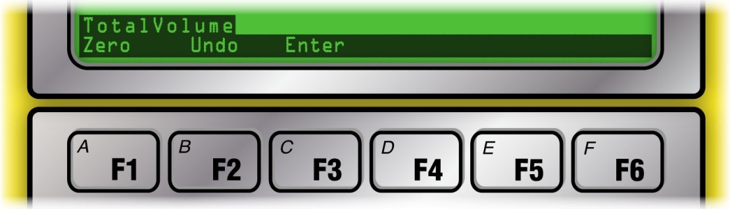
Now press F1 to zero out the volume. This option is used to clear out the total volume. This is sometimes needed when the pump has been idling for some time or if some slurry recirculation was performed before the beginning of the actual pumping operation. In such cases the user needs to zero out the volume. The zeroed volume can be undone by pressing the F2 key. If the pumped volume is known (for example in the beginning of a new stage) or if the user needs to otherwise set the total pumped volume to a new value press F3. This will give the user an opportunity to enter the new total volume.
Total Rate
The total rate is the seventh parameter (first on the second page) displayed on the Rapidlogger display. For double pump units the total rate is the sum of the pump rate from both pumps. If the Rapidlogger is used on a single pump unit then the total rate is the same as the pump rate of the first pump. The rate variables in the Rapidlogger cannot be zeroed or modified while the system is running a job. This feature has been intentionally designed to prevent errors in the totalized values.
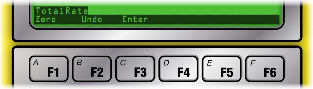
Pump 1 Total Volume & Pump 2 Total Volume
The pump 1 and pump 2 volumes are the fifth and sixth variables displayed on the Rapidlogger display. For double pump cementers these variables display the individual pump volumes. For single pumps the pump1 volume is the only variable used. In order to edit the pump 1 or pump 2 Total volumes, press F6 and then F4 for pump 1 or F5 for pump 2. Now press F1 to zero out the volume, F2 to undo the effects of zeroing or entering a new value or F3 to enter a new value for the volume,
When the Rapidlogger unit is operated in the fracturing mode, all of the on-screen menu options are specifically configured for fracturing operations. In this mode each Rapidlogger unit can support up to four pumps, however it is preferred to operate only two pumps for each Rapidlogger unit. Pumping pressure, density, total volume, total rate, pump rate 1, pump rate 2 are the parameters that are displayed on the screen. Pump rate 3, pump rate 4 are not displayed on the screen but are recorded and transmitted to the PC.
Once powered on the Rapidlogger starts displaying and recording data automatically. The user can access the fracturing menus by pressing F6. When F6 is pressed the following menu appears on the screen and the user can edit settings for pressure, density, total volume, and rate.

Pump Pressure
Pump pressure is the first parameter displayed on the Rapidlogger screen. The pump pressure on a fracturing unit is generally measured with a pressure transducer in the main treating line. In order to edit the pressure readings press F6 and then F1 from the main screen and the following menu will appear
Now press F1 to zero out the pressure. This option is used to clear out a small pressure offset from the variable when it is known that the pressure should be zero or atmospheric. In order to clear out the pressure offset or undo the zeroing of the pressure variable press F2. If the actual pressure is known such as due to a calibration or dead weight test or from a calibrated client pressure gage, and the Rapidlogger reading needs to match that calibrated reading, press F3 and the system will allow you to enter a new pressure value. Powering the system off and then on again will clear out this pressure offset value.
Pump 1, Pump 2, Pump 3, and Pump4 Rates
The pump 1 through and pump 4 rates are the next four parameters displayed on the Rapidlogger display. Pump rates cannot be edited during a job. This is necessary to prevent errors in the pump volume calculations being done.
Total Rate
The total rate is the sixth parameter displayed on the Rapidlogger display. If multiple fracturing pumps are being monitored with one Rapidlogger unit then the sum of the pump rates from the pumps is shown as the total rate. If the Rapidlogger is used on a single pump unit then the total rate is the same as the pump rate of the first pump. The rate variables in the Rapidlogger cannot be zeroed or modified while the system is running a job. This feature has been intentionally designed to prevent errors in the totalized values.
Total Volume
The total volume is the seventh parameter displayed on the Rapidlogger screen. The total volume is measured by means of a flowmeter or a pump stroke counter. In order to edit the total volume press F6 and then F3 from the main menu and the following menu will appear
Now press F1 to zero out the volume. This option is used to clear out the total volume. This is sometimes needed when the pump has been idling for some time before the beginning of the job or if some recirculation was performed before the beginning of the actual pumping operation. In these cases, the user needs to zero out the volume. The zeroed volume can be undone by pressing the F2 key. If the pumped volume is known (for example in the beginning of a new stage) or if the user needs to otherwise set the total pumped volume to a new value press F3. This will give the user an opportunity to enter the new total volume. (can not enter a new value of Total volume)
Proppant Density
The density is measured by means of a densitometer installed on the treating line. The proppant density is normally not displayed on the Rapidlogger screen. However, if the setup has been modified by the user to display proppant density on the local screen then proppant density readings can be edited. In order to do so press F6 and then F2 from the main screen and the following menu will appear
Now press F1 to zero out the density. This option is used to clear out any small offset in the density value variable when it is known that the density should be zero. In order to clear out the density offset or eliminate the zeroing process press F2. If the actual density is known, such as due to a calibration with pure water or from a calibrated client densitometer, press F3 and then you can enter a new density value which will be stored in the system only for that particular session. Powering the system off and then on again will clear out this density offset value.
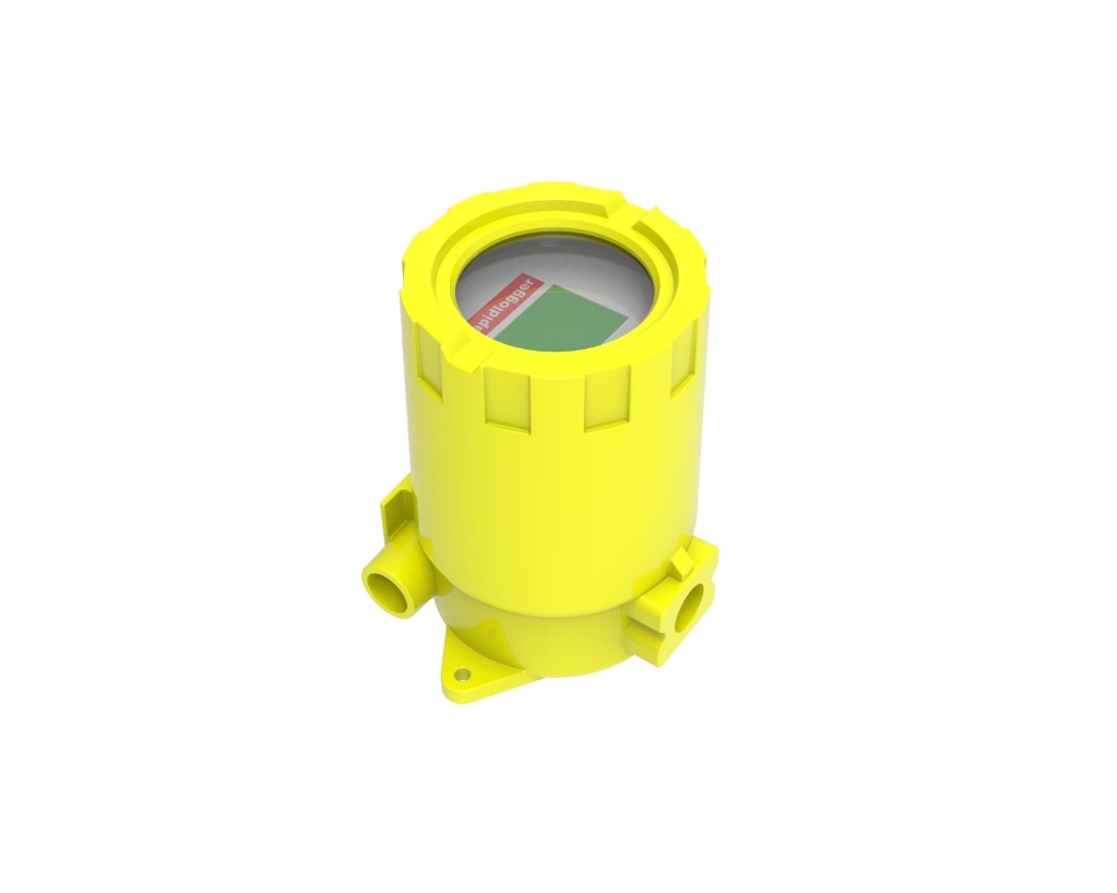
When the Rapidlogger is used as an explosion proof CT Injector remote device (Rapidlogger ExD). The same software and firmware will be used on the Rapidlogger ExD as the standard Rapidlogger. However, the setup would be different.
In this mode the Rapidlogger ExD is interfaced to one or two depth encoders and a wellhead pressure sensor. If two encoders are connected the Rapidlogger ExD runs the fastest wheel algorithm. This results in a much more accurate depth measurement than simply using one encoder and depth wheel.
In order to wire up the CT Injector mode, the A and B signal from one encoder would be wired in to the Q1A and Q1B terminals on the Digital Inputs terminal block. The second encoder should be wired in to the Q2A and Q2B terminals on the Digital Inputs terminal block. The power and ground of the encoder should be wired in to the GND and +V of the same terminal block.
The Well head pressure sensor should be wired in to the A1 terminal and the +V terminal of the Analog input terminal block.
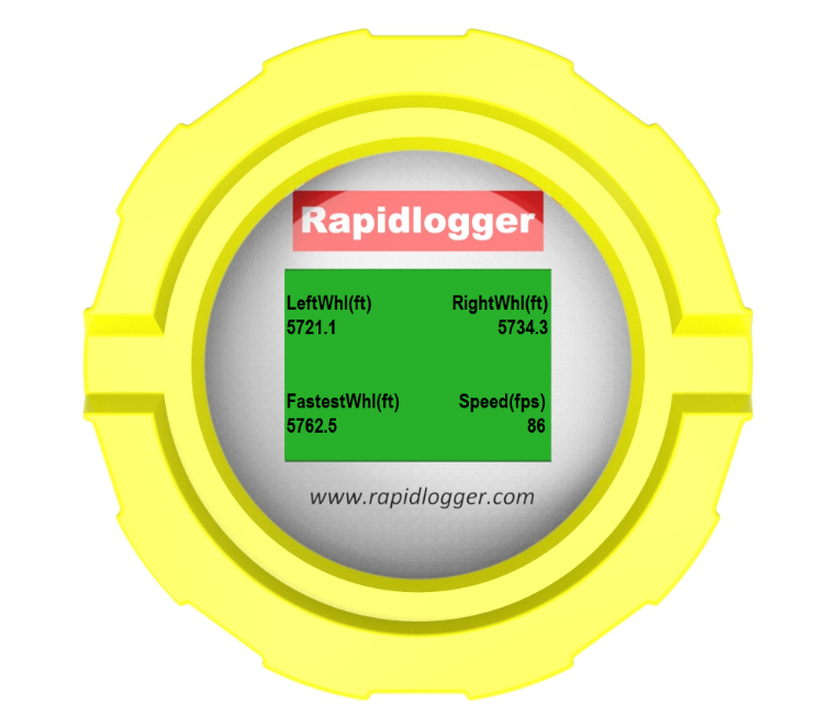
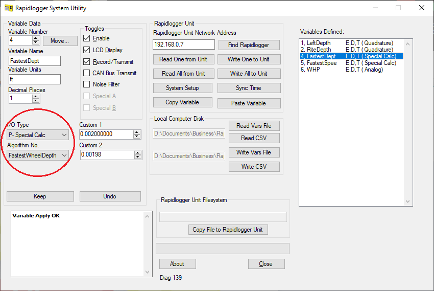
The fastest wheel algorithm can be programmed using the Rapidlogger Utility. It is available on the IO type drop down menu under Special Calc. Use Algorithm No FastestWheelDepth. The Custom 1 entry box should contain the Kfactor for the first encoder. The Custom 2 entry box should contain the Kfactor for the second encoder. Similarly, the speed should be selected using the algorithm FastestWheelSpeed. There are no multipliers required for speed.
The fastest wheel algorithm is available in Rapidlogger firmware starting from Version 9.9AP. Rapidlogger Utility version 4.67 or newer is required to setup the algorithm.
A four-conductor armored cable can be used to bring the wellhead data back to the safe area or monitoring station. This can be wired to use CAN bus or MODBUS RTU (as needed by the user). Alternatively, the ethernet connector inside the Rapidlogger ExD can be utilized to transmit the data over an armored ethernet cable. If an ethernet connection is utilized then the data can be transmitted using MODBUS-TCP, Rapidlogger Protocol, or WITS-0 as needed.
When the Rapidlogger is used as an explosion proof wellhead device (Rapidlogger ExD). The same software and firmware is used on the Rapidlogger ExD as the standard Rapidlogger. However, the setup would be different. In Wellhead Monitoring Mode the Rapidlogger is programmed for WHP, Flowrate and Valve position.

A four-conductor armored cable can be used to bring the wellhead data back to the safe area or monitoring station. This can be wired to use CAN bus or MODBUS RTU (as needed by the user). Alternatively, the ethernet connector inside the Rapidlogger ExD can be utilized to transmit the data over an armored ethernet cable. If an ethernet connection is utilized then the data can be transmitted using MODBUS-TCP, Rapidlogger Protocol, or WITS-0 as needed.

When the Rapidlogger Max is used as a drilling EDR then the setup is done at the Rapidlogger factory. This is because of the complexity of the setup. If the user wants to setup the drilling mode themselves then they can request a sample drilling mode setup file from Rapidlogger support.

The drilling specific special calculation algorithm that can be used are
ALGORITHM_SLIP_POS
ALGORITHM_PIPE_DPT
ALGORITHM_SLIP_LOAD
ALGORITHM_BIT_DPT
ALGORITHM_HOLE_DPT
ALGORITHM_TON_MILE
ALGORITHM_ROP
ALGORITHM_ROP_AVG
ALGORITHM_WOB
ALGORITHM_WOB_AVG
ALGORITHM_WOB_MAX
ALGORITHM_ROP_MAX
ALGORITHM_TDRPM
ALGORITHM_TDRPM_AVG
ALGORITHM_TDRPM_MAX
ALGORITHM_SPPress_MAX
ALGORITHM_CasePres_MAX
ALGORITHM_DiffPres
ALGORITHM_CircTime_Tot
ALGORITHM_TDTorq_AVG
ALGORITHM_MudVol_IN
ALGORITHM_MudVol_OUT
ALGORITHM_FastestWheelDepth
ALGORITHM_FastestWheelSpeed
When the Rapidlogger unit is operated in the slickline mode all of the on-screen menu options are specifically configured for slickline operations. Depth, speed, tension and wellhead pressure are the parameters that are displayed on the screen. The screen is configured to show these four parameters. However, the user can program additional parameters and configure the screen to show up to 6 parameters. More than 6 parameters can be recorded to the SD card.
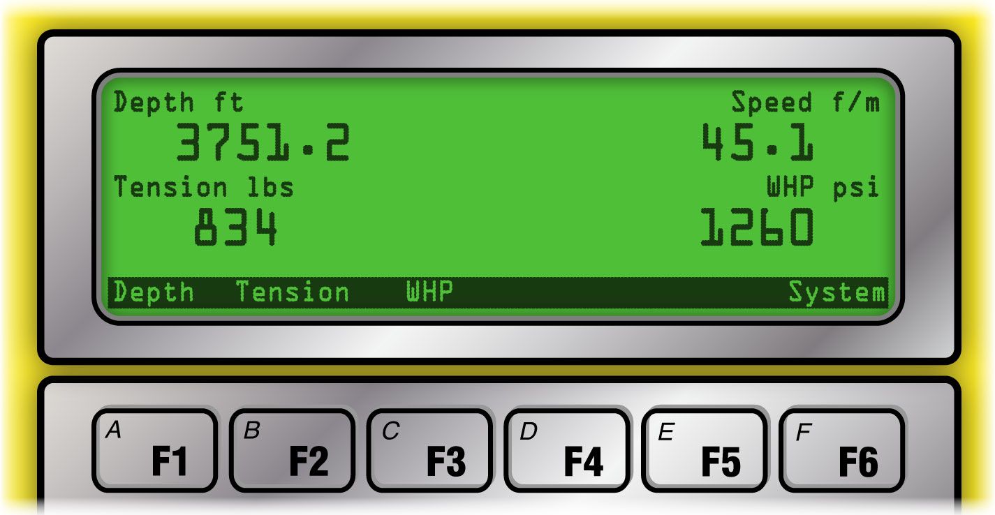
Depth
Depth is the first parameter displayed on the Rapidlogger screen when it is in the slickline mode. On a slickline unit depth is usually measured with a depth encoder mounted on the friction wheel. This encoder turns with the friction wheel and records the length of the slickline that has been paid out from the winch.

In order to edit the Depth variable on the Rapidlogger press F6 and then F1 from the main menu and the following menu will appear.
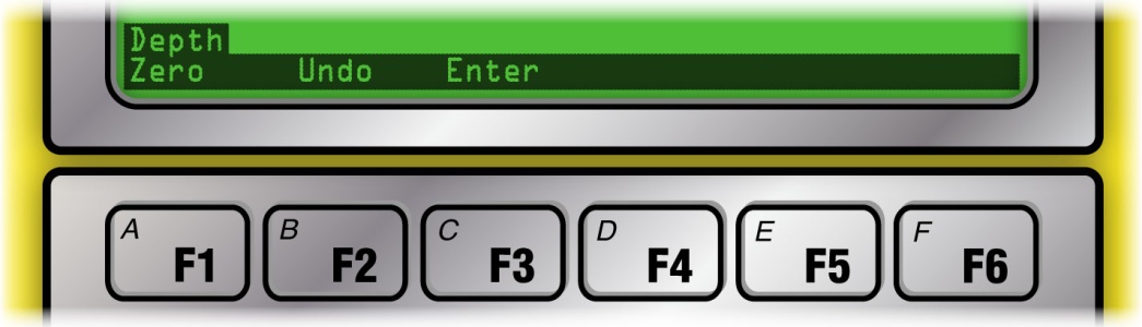
Now press F1 to zero out the depth. This is useful at the beginning of a job when the slickline drum has been rotated and the depth is not zero or when the tool is tagged to the Kelly bushing or any other reference depth. The zero offset is applied to that job only and is not stored in the system once it is powered down. The zeroed depth value can be undone by pressing F2. This causes the applied depth offset to be erased and the depth becomes the same as before the zeroing. If a new depth needs to be entered such as when the tool is tagged to a known downhole depth, then pressing F3 from this menu allows the operator to enter a new depth. This new depth is stored as the depth offset in the system for this job only and is erased when the unit is powered down.
Speed
Speed is the second parameter displayed on the Rapidlogger screen when it is in the slickline mode. On a slickline unit speed is calculated from the change in depth. The speed variable in the Rapidlogger cannot be zeroed or modified while the system is recording a job. This feature has been intentionally designed to prevent errors in the depth value.
Tension
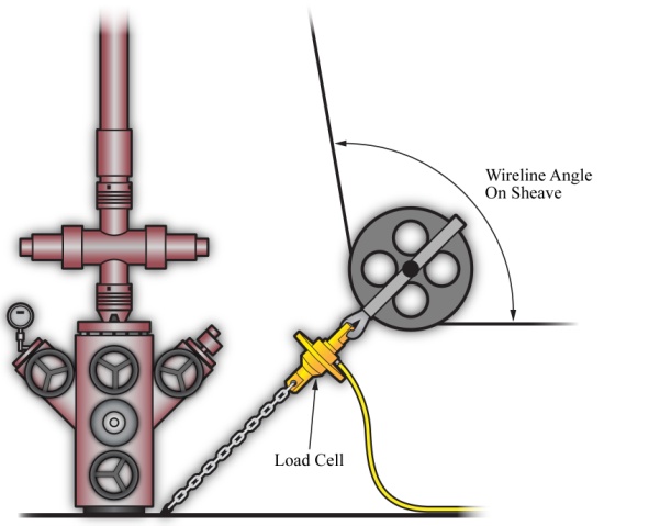
Tension is the third parameter displayed on the Rapidlogger screen when it is in the slickline mode. On a slickline unit, line tension is usually measured by means of a load cell mounted on the bottom sheave. The slickline passes under the bottom sheave, pulling tension on to the load cell.
This electrical signal for line tension is transmitted to the Rapidlogger unit, where it is digitized, displayed and recorded. The tension variable on the Rapidlogger can be adjusted to account for small variation in the tension reading due to calibration error or temperature. In order to edit the tension variable on the Rapidlogger from the main menu, press F6 and then F2 and the following menu will appear.

Now press F1 to zero out the tension. Care must be taken while zeroing out the line tension. If a large number is zeroed out then the slickline unit operator will no longer be aware of the true line tension. Zeroing out line tension is useful at the beginning of a job when the slickline tension is off by some small amount. The zeroed tension value can be undone by pressing F2. This causes the applied tension offset to be erased and the tension becomes the same as before the zeroing. If a new tension needs to be entered, pressing F3 from this menu allows the operator to enter a new tension. This new tension is stored as the tension offset in the system for this job only and is erased when the unit is powered down.
Wellhead Pressure
Wellhead pressure (WHP) is the fourth parameter displayed on the Rapidlogger screen when it is in the slickline mode. The wellhead pressure on a slickline unit is generally measured with a pressure transducer installed on a pressure line connected to the wellhead. In order to edit the wellhead pressure readings, press F6 and then F3 from the main screen and the following menu will appear
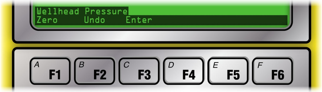
Now press F1 to zero out the WHP. The zeroed WHP value can be undone by pressing F2. If an accurate value of WHP is known such as from a calibrated client sensor, then the new WHP can be entered in to the Rapidlogger by pressing F3 from this menu. This new WHP is stored in the system for this job only and is erased when the unit is powered down.
When the Rapidlogger unit is operated in the coiled tubing mode all of the on-screen menu options are specifically configured for coiled tubing operations. Depth, speed, weight, circulating pressure, pump rate, and pump volume are the parameters that are displayed on the screen. The screen is configured to show these six parameters.
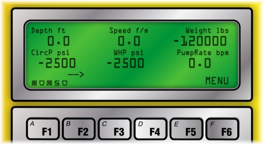
However optionally the user can choose to show only 4 parameters and setup the system in this manner. Once the user presses the F6 key the following menu appears and the user can then proceed to make further selections.

Depth
Depth is the first parameter displayed on the Rapidlogger screen when it is in the Coiled Tubing mode. On a coiled tubing unit depth is usually measured with a depth encoder mounted on a friction wheel that runs against on the coiled tubing. The encoder turns with the friction wheel and records the length of the coiled tubing that has passed through the CT injector. A typical coiled tubing injector encoder installation is shown below.
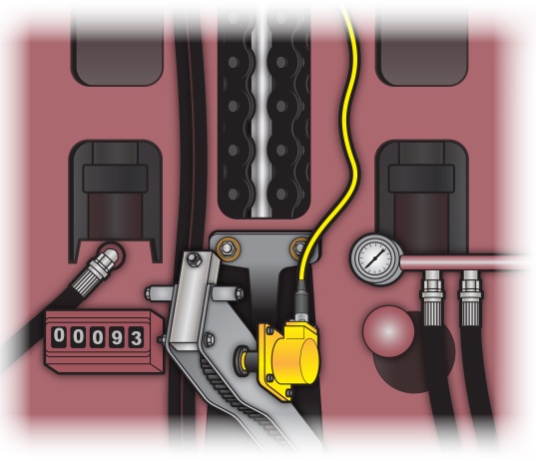
In order to edit the Depth variable on the Rapidlogger press F6 and then F1 from the main menu and the following menu will appear.
Now press F1 to zero out the depth. This is useful at the beginning of a job when the coiled tubing is being moved up and down while trying to install a BHA assembly on the end. Thus, the depth is not zero when the coiled tubing BHA or connector is tagged to the stripper or other reference depth. The zero offset is applied to that job only and is not stored in the system once it is powered down. The zeroed depth value can be undone by pressing F2. This causes the applied depth offset to be erased and the depth becomes the same as before the zeroing. If a new depth needs to be entered such as when the tool is tagged to a known downhole depth then pressing F3 from this menu allows the operator to enter a new depth. This new depth is stored as the depth offset in the system for this job only and is erased when the unit is powered down.
Speed
Speed is the second parameter displayed on the Rapidlogger screen when it is in the coiled tubing mode. On coiled tubing units speed is calculated from the change in depth. The speed variable in the Rapidlogger cannot be zeroed or modified while a job is being recorded. This feature has been intentionally designed to prevent errors in the depth value.
Weight
Weight or coiled tubing hanging weight is the third parameter displayed on the Rapidlogger screen when it is in the coiled tubing mode. On a CT unit the weight is measured by means of a load cell mounted on the injector. Thus, part of the combined weight of the coiled tubing and injector sits on the load cell. A typical load cell installation on a coiled tubing injector is shown below.
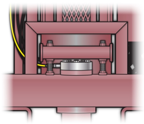
Sometimes on a high pressure well (snubbing operation) well pressure can push up on the coiled tubing causing negative weight readings on the load cell.
This electrical signal for the weight is transmitted to the Rapidlogger unit, where it is digitized, displayed and recorded. The weight variable on the Rapidlogger can be adjusted to account for small variation in the weight reading due to calibration error or temperature. In order to edit the weight variable on the Rapidlogger from the main menu press F6 and then F2 and the following menu will appear.
Now press F1 to zero out the weight.
WARNING: Care must be taken while zeroing out the CT Weight. If a large number is zeroed out then the coiled tubing unit operator will no longer be aware of the true CT weight.
Zeroing out CT weight is useful at the beginning of a job when the CT weight is incorrect by a small amount. The zeroed weight value can be undone by pressing F2. This causes the applied weight offset to be erased and the weight becomes the same as before the zeroing. If a new weight needs to be entered, then pressing F3 from this menu allows the operator to enter a new weight. This new weight is stored as the tension offset in the system for this job only and is erased when the unit is powered down.
Circulating Pressure
Circulating pressure or pump pressure is the fourth parameter displayed on the Rapidlogger screen. The pump pressure on a CT unit is generally measured with a pressure transducer in the main treating line installed before the CT reel swivel. In order to edit the pressure readings, press F6 and then F3 from the main screen and the following menu will appear
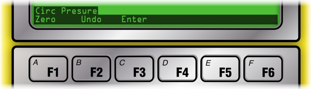
Now press F1 to zero out the pressure. This option is used to clear out a small pressure offset from the variable when it is known that the pressure should be zero or atmospheric. In order to clear out the pressure offset or eliminate the zeroing of the pressure variable press F2. If the actual pressure is known such as due to a calibration or dead weight test or from a calibrated client pressure gage, and the Rapidlogger reading needs to match that calibrated reading, press F3 and the system will allow you to enter a new pressure value. Powering the system off and then on again will clear out this pressure offset value.
Pump Rate
The pump rate is the fifth parameter displayed on the Rapidlogger display. The rate variables cannot be zeroed or modified during a job. This feature has been intentionally designed to prevent errors in the totalized values.
Total Volume
The total volume is the seventh parameter (first on next screen) displayed on the Rapidlogger screen (not shown in menu page). The total volume is measured by means of a flowmeter or a pump stroke counter. In order to edit the total volume press F6 and then F4 from the main menu and the following menu will appear
Now press F1 to zero out the volume. This option is used to clear out the total volume. This is sometimes needed when the pump has been idling for some time or if some recirculation was performed before the beginning of the actual pumping operation. In these cases, the user needs to zero out the volume. This can also be used to zero out the pumped volume before the beginning of the next stage. The zeroed volume can be undone by pressing the F2 key. If the pumped volume is known (for example in the beginning of a new stage) or if the user needs to otherwise set the total pumped volume to a new value press F3. This will give the user an opportunity to enter the new total volume.
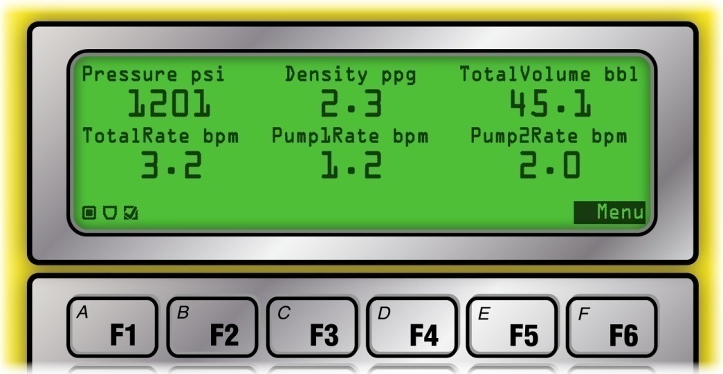
Regardless of the operating mode that the Rapidlogger is in, the common system options are always available. The common operation options include
USB
Network Settings
Display Settings
Time Setting
Variable Settings
Factory Reset
Diagnostics
Pressing F6, F6 from the main screen brings up the following system menu. This menu allows access to the common system options.

USB
In order to copy job data files from the Rapidlogger to an external USB memory stick, insert a USB memory stick into the USB port. This USB stick should be empty and should have been formatted with FAT file system on a PC. Press F6 to bring up the main menu, F6 again to select USB options. From here it is possible copy the last job file or select a file from all of the job files.
In order to copy just the last job file to the USB flash drive press F6 from this menu again to select the Copy Last File option. The copy process can take several minutes depending on the size of the file. The USB stick should not be removed until the screen indicates that the file copy is complete. Removing the USB stick while in the middle of the copy process and may require the unit to be reset before it can properly copy files to USB sticks again.
In order to select the file to copy from the list of all of the job files recorded on the SD card, press F4 from this menu again to go to the Copy Select File option. Now the screen will display the name of a job file. If this is the file you want to copy press Enter, if you want to exit the copy process press F6. Pressing any other key select and displays the name of the next job file. Keep pressing a key until you see the name of the file that you would like to copy to the USB flash drive. Once you see the file name you want to copy press Enter. The copy process for a file can take up to 2 minutes. Once the screen indicates that the copy is complete and the activity light on the flash drive has stopped flashing, the stick can be removed.
The file names on the Rapidlogger internal SD card are meant to indicate the date of the job file. So, a file name 15Jul08.TXT means that it is for a job that took place on July 15, 2008. This allows the user to easily know the file name for a job that took place on a certain day.
Network Settings
Changing network settings is an advanced user option and should not be done by users who are not familiar with Ethernet network settings. In order to edit or change the network setting press F6, F6, F1 from the main menu. The system will now give menu options to enter the IP address, gateway address, and the network mask. Press enter after entering each number. Press F6 in order to skip entering a number at any prompt. The previous value is retained for that number. The newly entered network settings come in effect after a system power cycle. The default network settings for the Rapidlogger system are as follows.
IP: 192.168.000.005 Gateway: 192.168.000.001 Netmask: 255.255.255.000
These settings are also restored after a factory reset. Entering an IP address of 000.000.000.000 puts the Rapidlogger in DHCP mode. This mode should only be used when there is a router or server available on the network that has DHCP server capabilities.
Display Setting
The display settings can be modified from both the Rapidlogger Utility program and the Rapidlogger front panel.
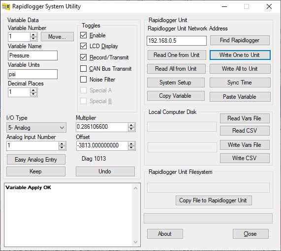
When using the Rapidlogger Utility program, pressing the System Setup button from the main window brings the user to the following screen. Here they can change the number of displayed variables and the Operating Mode. The valid options are 2, 4, and 6 variables to be displayed on the Rapidlogger LCD screen. Enter the number of parameters that you would like to see displayed on the LCD screen.
DisplayVariablesDisplayVariablesOperating ModeOperating Mode

The display setting can also be changed from the Rapidlogger front panel. In order to change the display settings from the front panel press F6, F6, F2 from the main menu. The system will now prompt you to enter the number of display parameters. Enter the number of variables and press Enter.
Time Setting
The date and time can be synchronized easily from the PC via the RapidVu and Rapidlogger Utility programs. From the Rapidlogger Utility program main screen the user can press Sync Time button to synchronize the Rapidlogger internal clock to the PC system clock. In order to edit or change the Rapidlogger job clock press F3. The system will now prompt you to enter the date and time. Normally there is no need to enter the time on the Rapidlogger system from the keypad. The system clock is battery backed and retains the correct time and date for up to 5 years.
Variable Settings
The variable settings should not be attempted by novice Rapidlogger users.
Changing variable settings and programming or erasing variables can be done both from the Rapidlogger Utility program and Rapidlogger front panel. The Rapidlogger Utility program allows very easy setup of the various variables and settings on the unit. The front panel option should only be utilized by an expert user.
ReadVariableReadVariable

From the Rapidlogger Utility main screen the variable number to be viewed or modified can be selected. This variable can then be read in from the Rapidlogger unit by pressing the Read One from Unit button. The settings for the selected variable will then be displayed on the screen. The various parameters associated with the variable can then be changed as needed. Each variable number has a name, unit label, number of decimal places, input type, input number, multiplier, and offset associated with it. In addition, the enable, display and record settings can be toggled on each variable. Another option that the user has is to use the Read All from Unit button and retrieve all variables at once from the Rapidlogger unit. The variables can be modified and saved either one by one or all at once using the Write buttons.
It is also possible to edit or change the Rapidlogger job variables from the front panel. To do this press F6, F6, F4 from the main menu. The following system menu will now be displayed.
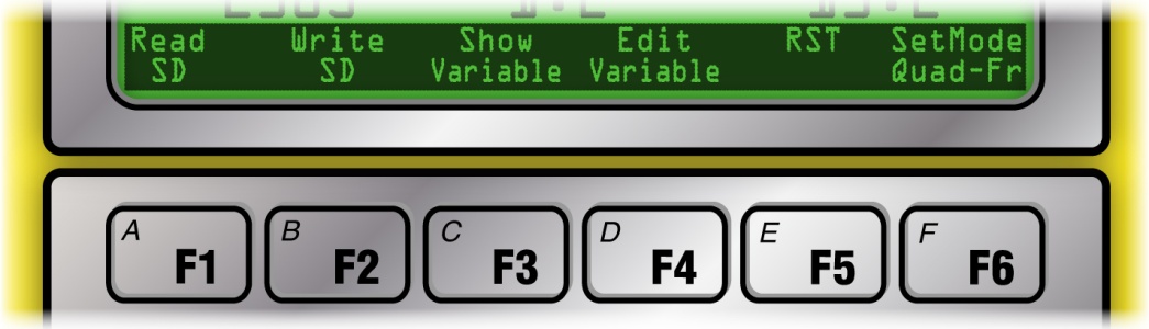
Press F3 to show the setting for a given variable and Press F4 to edit the variable settings.
WARNING: The option to edit variable settings from the front panel is for advanced users only and even then, it should only be used if the Rapidlogger Utility program is not available. Incorrect use will cause the variable setting to be incorrect and WILL cause the recorded variable values to be very different from the real values.
Press F5 to reset the Rapidlogger setup to one of the preset setups. Selecting one of the options available would overwrite and erase the current setup and replace it with the new selected one.
It is also possible to read the entire set of variables from the SD card. Press F1 to load the complete system variable setup file from the SD card. A file named "SETUPIN.RLV" is read from the SD memory card and its contents are loaded in the system.
WARNING: The settings for all job variables will be loaded from the SD card and will overwrite the existing variable setup.
Normally, this option is only used during system setup. In order to save the entire setup to the SD card, press F2. This will save the complete set of system variables to the SD card. A file named "SETUPOUT.RLV" is written to or created on the SD memory card.
WARNING: The contents of the SETUPOUT.RLV file on the SD card are overwritten and replaced by the copy of the job variables from the system.
Normally this option is only used during system setup to back up a system that has been properly set up.
Factory Reset
In order to perform a factory, reset of the Rapidlogger system press F6 from the system menu. The following menu will now be displayed.
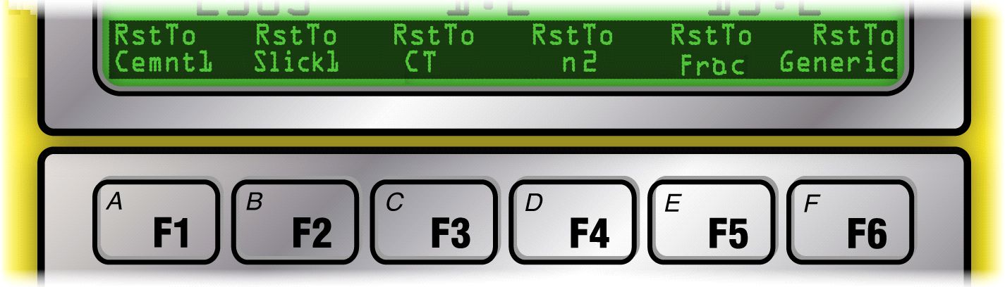
By pressing the appropriate key, the user can perform a factory reset of the Rapidlogger to one of the preprogrammed factory modes. These include Cementing, Slickline, Coiled Tubing, Nitrogen, and Fracturing.
WARNING: The customization and settings for all job variables will be erased and the system will be reset to the selected factory programmed mode.
Diagnostics
The Rapidlogger Unit has a built-in diagnostics mode in which the raw sensor inputs can be viewed to ease troubleshooting. G
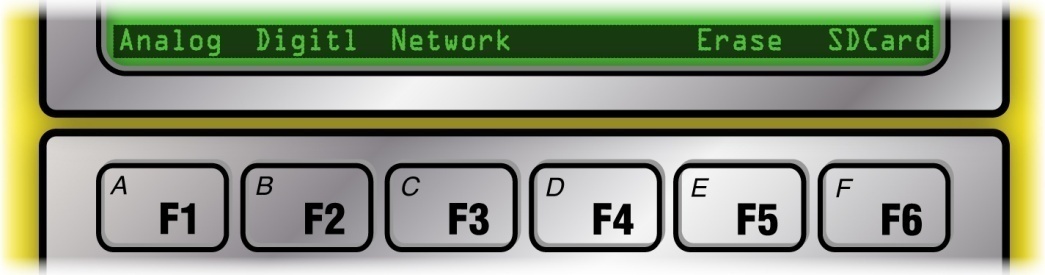
The diagnostics mode for analog sensors can be accessed from the front panel keypad (Press F6, F6, F5, F1, F1). The diagnostics mode for frequency sensors can be accessed from the front panel keypad (Press F6, F6, F5, F2). The diagnostics mode for Ethernet networks can be accessed from the front panel keypad (Press F6, F6, F5, F3). In each case a screen appears on the LCD that displays the various sensor values.
During a cementing, CT, slickline or pumping job it can be beneficial to log comments in the data file to indicate the beginning, or ending of different activities or events. There are a large number of commonly used job comments preprogrammed into the Rapidlogger Unit that can be logged by simply entering the comment number from the front panel.

From the main menu the user can press F7 (which is also the G key). A prompt appears on the bottom of the screen instructing the user to enter the comment number. The user can then enter the comment number that they would like to log and then press Enter. If the user waits too long to enter the comment number then the prompt erases itself and the display goes back to the main menu. Any comments that are logged in this manner are stored in the job data file and printed automatically with the RapidVu job reports. The following comments are available in the Rapidlogger Unit.
| # | Job Comment Message | # | Job Comment Message | # | Job Comment Message |
|---|---|---|---|---|---|
| 1 | Bump Closing Plug | 62 | Remark | 123 | Started Water |
| 2 | Bump Dart | 63 | Reset Selected Totals | 124 | Started Wiper Trip |
| 3 | Bump Plug | 64 | Reset Stage Totals | 125 | Stopped Acid |
| 4 | Bump Stage Plug | 65 | Reset Volume | 126 | Stopped Brine |
| 5 | Bump Top Plug | 66 | Screened Out | 127 | Stopped Cement Slurry |
| 6 | Change Mud Weight | 67 | Sensor Calibrated | 128 | Stopped Circulation |
| 7 | Change Parameter Name | 68 | Sensor Zeroed | 129 | Stopped Diesel |
| 8 | Change Pump Rate | 69 | Set Rams | 130 | Stopped Displacement |
| 9 | Change Sensor Calibration | 70 | Shutdown | 131 | Stopped Diverter |
| 10 | Decrease Rate | 71 | Stage t Perfs | 132 | Stopped Drilling/Milling |
| 11 | Depth Corrected | 72 | Stage Changed | 133 | Stopped First Stage |
| 12 | Depth Correlation Event | 73 | Started Acid | 134 | Stopped Fluid |
| 13 | Depth Modified | 74 | Started Brine | 135 | Stopped Flush |
| 14 | Depth Reset | 75 | Started Cement Slurry | 136 | Stopped Injection |
| 15 | Depth Zeroed | 76 | Started Circulation | 137 | Stopped Inject nonreact Fluid |
| 16 | Dropped Ball/Dart | 77 | Started Diesel | 138 | Stopped Inject reactive Fluid |
| 17 | Dropped Bottom Plug | 78 | Started Displacement | 139 | Stopped Job |
| 18 | Dropped Closing Plug | 79 | Started Diverter | 140 | Stopped Logging |
| 19 | Dropped Opening Plug | 80 | Started Drilling/Milling | 141 | Stopped Mixing Lead Slurry |
| 20 | Dropped Stage Plug | 81 | Started First Stage | 142 | Stopped Mixing Scav Slurry |
| 21 | Dropped Top Plug | 82 | Started Fluid | 143 | Stopped Mixing Tail Slurry |
| 22 | Dropped Wiper Plug | 83 | Started Flush | 144 | Stopped next PPA Proppant |
| 23 | Ended Acid | 84 | Started Injection | 145 | Stopped Next Stage |
| 24 | Ended Brine | 85 | Started Injection Nonreact Fluid | 146 | Stopped Nitrogen |
| 25 | Ended Cement Slurry | 86 | Started Injection Reactive Fluid | 147 | Stopped Pad |
| 26 | Ended Circulation | 87 | Started Job | 148 | Stopped POOH |
| 27 | Ended Diesel | 88 | Started Logging | 149 | Stopped Pressure Test |
| 28 | Ended Displacement | 89 | Started Mixing Lead Slurry | 150 | Stopped Proppant |
| 29 | Ended Fluid Stage | 90 | Started Mixing Scav Slurry | 151 | Stopped Pull Test |
| 30 | Ended Job | 91 | Started Mixing Tail Slurry | 152 | Stopped Pumping Acid |
| 31 | Ended Logging | 92 | Started next PPA Proppant | 153 | Stopped Pumping Brine |
| 32 | Ended Mud Acid | 93 | Started Next Stage | 154 | Stopped Pumping Foam |
| 33 | Ended Mud | 94 | Started Nitrogen | 155 | Stopped Pumping Gel |
| 34 | Ended Nitrogen | 95 | Started Pad | 156 | Stopped Pumping Mud Acid |
| 35 | Ended Nitrogen | 96 | Started POOH | 157 | Stopped Pumping Mud |
| 36 | Ended Oil | 97 | Started Pressure Test | 158 | Stopped Pumping Next Fluid |
| 37 | Ended Over-flush | 98 | Started Proppant | 159 | Stopped Pumping Nitrogen |
| 38 | Ended Pre-flush | 99 | Started Pull Test | 160 | Stopped Pumping Oil |
| 39 | Ended Reverse Circulation | 100 | Started Pumping Acid | 161 | Stopped Pumping Over-flush |
| 40 | Ended Slurry | 101 | Started Pumping Brine | 162 | Stopped Pumping Pre-flush |
| 41 | Ended Spacer | 102 | Started Pumping Foam | 163 | Stopped Pumping Proppant |
| 42 | Ended Stage | 103 | Started Pumping Gel | 164 | Stopped Pumping Spacer |
| 43 | Ended Wash | 104 | Started Pumping Mud Acid | 164 | Stopped Pumping Spacer |
| 44 | Ended Water | 105 | Started Pumping Mud | 165 | Stopped Pumping Wash |
| 45 | Maximum Depth | 106 | Started Pumping Next Fluid | 166 | Stopped Pumping Water |
| 46 | Maximum Pressure | 107 | Started Pumping Nitrogen | 167 | Stopped Pumping |
| 47 | Maximum Rate | 108 | Started Pumping Oil | 168 | Stopped Reverse Circulation |
| 48 | Modified Pump Schedule | 109 | Started Pumping over-flush | 169 | Stopped RIH |
| 49 | Modified Totalizer | 110 | Started Pumping pre-flush | 170 | Stopped Second Stage |
| 50 | Pause | 111 | Started Pumping Proppant | 171 | Stopped Selected Totals |
| 51 | Perforating | 112 | Started Pumping Spacer | 172 | Stopped Sensor Check |
| 52 | Plug Balanced | 113 | Started Pumping Wash | 173 | Stopped Squeeze |
| 53 | Remark BHA | 114 | Started Pumping Water | 174 | Stopped Tripping |
| 54 | Remark Bleed Off Pressure | 115 | Started Pumping | 175 | Stopped Water |
| 55 | Remark Cementing Event | 116 | Started Reverse Circulation | 176 | Stopped Wiper Trip |
| 56 | Remark CT Event | 117 | Started RIH | 177 | Weight Modified |
| 57 | Remark Fracturing Event | 118 | Started Second Stage | 178 | Weight Zeroed |
| 58 | Remark Milling | 119 | Started Selected Totals | ||
| 59 | Remark Pumping Event | 120 | Started Sensor Check | ||
| 60 | Remark Rig Event | 121 | Started Squeeze | ||
| 61 | Remark Slickline Event | 122 | Started Tripping |
RapidVU is software that can be used to gather data directly from a Rapidlogger connected to the computer with an Ethernet cable. With RapidVU, you can view a job’s progress, analyze previous jobs and generate automatic job reports for different types of jobs. Although you can use the program at any screen resolution, RapidVU is set up to display best on screens that are 1280x1024 pixels or higher.
RapidVU can communicate with WITS and ModBus, or it can read data directly from a file.

Installing and Starting RapidVU
You can install RapidVU on a personal computer with Windows 10, Windows 8 or Windows 7. The Rapidlogger device includes a flashdrive with the RapidVU software.
To install RapidVU:
To start RapidVU:
Choose Windows Start > All Programs > Rapidlogger Systems > RapidVU.
TIP: If you use RapidVU frequently, create a RapidVU shortcut and place the icon on the Windows desktop. If you have a RapidVU icon on the desktop, double-click it to start RapidVU.
Periodically, the RapidVU software gets updated. You can download updates from the www.rapidlogger.com site.
To update RapidVU:
Setting Up RapidVU
The RapidVU software was developed as a data viewer for Rapidlogger. You can also use it to view data collected with other devices.
User Modes of the RapidVU software
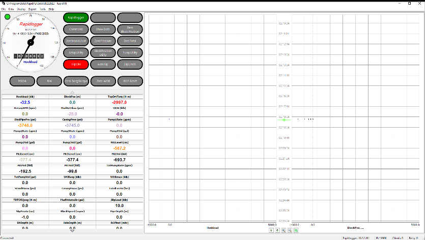
The RapidVU software has 4 main modes of operation.
The Standard mode is used for most normal operations

The Drilling Depth mode is used by the driller on a touch screen display to conduct drilling operations

The Drilling Multidial mode is used by the tool pusher and other personnel on a touch screen display to conduct support operations
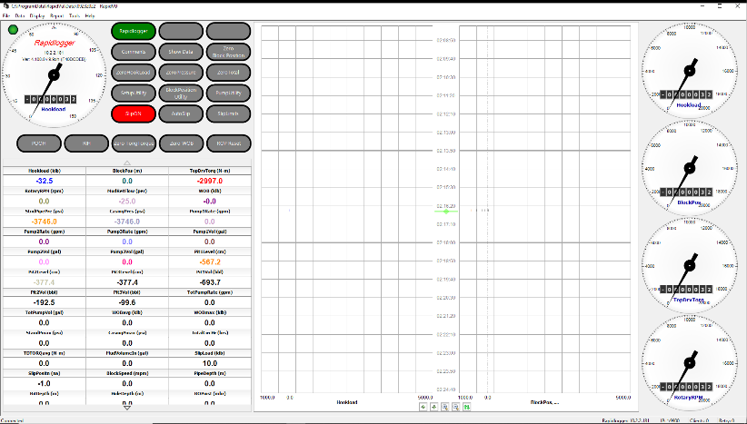
The Drilling Backoffice mode is used by the backoffice personnel on a touch screen display to prepare job reports etc.
Using RapidVU with Rapidlogger
There are several ways to use RapidVU with Rapidlogger:
To learn the IP address of a computer:
NOTE: This procedure is for Windows 7. Other versions of Windows may have a different procedure.
WARNING: Only knowledgeable users and IT personnel should change network settings. These settings should not be changed by users who are not familiar with Ethernet network settings.
To set up Rapidlogger as a direct connection to a computer with RapidVU installed:
By default, RapidVU is set up to work with Rapidlogger with a default IP address of 192.168.0.5. To make adjustments to the IP address, see “Using RapidVU Tools” later in this section.
To receive data from a directly connected Rapidlogger device:
RapidVU starts recording data from Rapidlogger. To stop recording data, choose Data > Stop Recording.
You can save data from the Rapidlogger SD card or other devices and read the data in RapidVU. To learn how to save data from the SD card, see “Using RapidVU Tools” later in this section.
To read data from a *.txt file:
RapidVU starts recording data from the data file. To stop recording data, choose Data > Stop Recording.
To record data from a Rapidlogger device on a network or server:
RapidVU starts recording data from the Rapidlogger. To stop recording data, choose Data > Stop Recording.
Using RapidVU with WITS
If you have devices that use the WITS 0 standard, RapidVU can read and interpret the data. RapidVU assumes that any WITS device is connected to the first available COM port. The COM port number can be changed from the pull-down menu.
NOTE: By default, RapidVU shows most recently saved mapping in the Dialog dialog box.
To receive data from a WITS 0 device:
To save an edited mapping to use again:
Viewing Data
By default, the main RapidVU window has two sections: the data acquisition section on the left and the data recording section on the right.
The main window, by default, also shows a status bar at the bottom.

Data Acquisition Section
The data acquisition section has a gauge at the top showing the measurement that was set up in the Rapidlogger. The round gauge shows the general value and the numeric indicator gives the specific value. You determine which measurement shows in the gauge by using the Rapidlogger Setup Utility. Above the gauge on the left, a green indicator shows that RapidVU is recording data. The indicator is red when not recording.
The variable boxes below the gauge show data from each sensor used with Rapidlogger. (For example, you may have sensors for the pump pressure and the pump rate.)
If you click the value in a Var box, you can reset the value to zero, change the value or undo any change you’ve made.
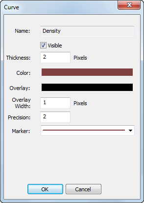
If you right-click a Var box, you open the Curve dialog box where you can specify options for showing that variable on a graph. For example, you can change the line’s color, marker and thickness for representing that variable in the line chart.
You can also specify the number of decimal places that appear for the value in its Var box by adjusting the Precision value. (For example, a Precision value of 1 shows one decimal place.)
To not view the variable’s data on a line chart, clear the Visible check box.
Data Recording Section
By default, RapidVU shows four line charts. If there are more than four variables to display, you can have RapidVU show multiple lines on a specific chart (or track) to see plots of data from all sensors.
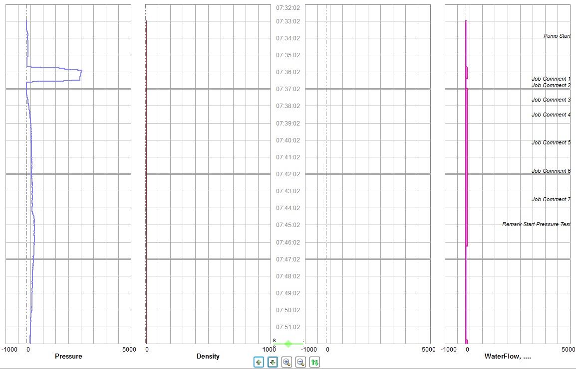
NOTE: RapidVU also has an Advanced Graph view that consolidates the charts. For details about viewing it, see “Using RapidVU Tools” later in this section.
At the bottom of the Data Recording section, you can use the buttons to control how you view the charts.

You use the commands on the Display menu to customize the Data Recording section.
Choosing 2 Charts on the Display menu replaces the four charts with just two. To return to the four charts view, choose 4 Charts. When you change the number of charts, you must restart RapidVU to have the change take effect.
You can also switch to full screen mode by choosing Display > Full Screen or by pressing F11. Full screen mode removes the Windows title bar, the menu bar, the status bar and the scroll bar. To return to normal display mode, press Esc.
To clear the data from all charts, choose Display > Clear Chart.
To refresh all charts, choose Display > Refresh Chart.
You use the options on the Axis tab in the Chart Options dialog box to customize the appearance of the charts. RapidVU automatically lists all sensor variables that it reads and assigns a color and a track for each sensor on the right side of the Axis tab.

To customize the y axis for all charts:
To customize the x axis for individual charts:
On the right size of the Axis tab, you can customize how each variable appears on the charts.
To customize how RapidVU plots a variable:
On the bottom left are the customization tabs. The tabs for Pressure, Depth, Working Rate, Working Volume and Casing Pressure and can be customized to be labeled as follows:
In the Chart Options dialog box, you can also customize the Advanced Graph view, adjust the running average, and specify an overlay file. For information about the Advanced Graph view, see “Using RapidVU Tools” later in this section.
Status Bar
A status bar appears at the bottom of the RapidVU window. On the right side of the status bar, a green indicator shows that RapidVU is recording data. The indicator is red when not recording. To the left of the recording status indicator, the status bar shows the IP address and other information about the most recent data recording. The left side of the status bar shows RapidVU’s status.
Switching Job Types
Rapidlogger and RapidVU provide four different job types: Cementing, Slickline, Pumping and Coiled Tubing. See sections 2.1 – 2.4 in this chapter for information about these Rapidlogger modes. RapidVU automatically determines the job type from Rapidlogger. You may need to adjust the job type before generating a report.
To change the job type, choose Report > Report Generate > Job Type.

Adding Comments
With RapidVU you can add one or more comments to a chart at any point. RapidVU provides a range of default comments that you can add, such as “Bump Closing Plug” or “Change Mud Weight,” but you can add your own comments if you wish.
NOTE: The default comments are common for Rapidlogger and RapidVU. You can specify default comments directly with the hardware. See Section 2.6 in this chapter for a list of default comments.
With RapidVU you can add default comments, add custom comments, edit existing comments or remove comments.
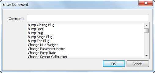
To add a comment:
To edit or remove a comment:
Generating Reports
RapidVU creates reports based upon the recorded data, the information in the Job Information dialog box and the active chart view (the main window or the Advanced Graph window). Each report is a Microsoft Word *.docx file with a name based on the specified job type and the current date (for example, Cementing-02062014.docx). RapidVU saves each report in the Documents/RapidVu/Reports folder.
NOTE: A RapidVU report is compatible with Microsoft Word 2007-2013 (*.docx files).
In addition to the *.docx file generated as a report, RapidVU automatically saves the recorded data in a CSV file (comma-separated value file) in the Documents/RapidVu/Data folder. You can use this CSV file to import data into Microsoft Excel (or any spreadsheet program that reads CSV files) for advanced plotting and analysis. RapidVU names the data file with the current date (for example, 02072014.csv). If there are multiple data files with the same date, RapidVU appends a number (-n) to the file name.
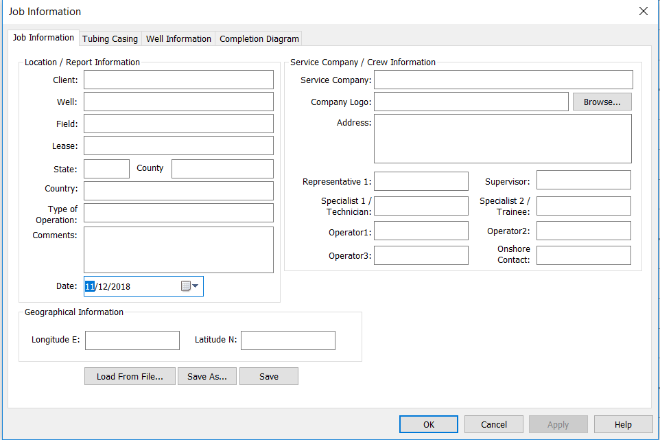
To enter new information about a job:
NOTE: RapidVU saves job information in the Documents/RapidVu/Data folder. These files are *.rlg files.
To re-load existing job information for a report:
To generate and view a report:

Using RapidVU Tools
The Tools menu has commands for interfacing with Rapidlogger, for viewing consolidated charts and for using special utilities (Rapid VQI and Rapidlogger Setup Utility).
Adjusting Rapidlogger
After you have downloaded data from Rapidlogger, you should erase the internal SD card periodically to keep space available for new job recordings. In general, the SD memory card should be erased with RapidVU (or from the front panel menus on Rapidlogger) at least once every 10–20 jobs. Erasing the SD card ensures that sufficient space is available and can prevent data corruption or loss.
By default, the Rapidlogger System Hardware dialog box shows an IP address of 192.168.0.5 for Rapidlogger. If, for some reason, that is not the IP address for Rapidlogger, you can adjust the IP address in the Host box.

To erase the SD card:
Occasionally, when actively recording, Rapidlogger may get out of sync with RapidVU. To re-synchronize Rapidlogger, click the Sync Time button in the Rapidlogger System Hardware dialog box.
If you have changed the IP address for the Rapidlogger in the Host box, you may need to click the Find button for RapidVU to connect to the Rapidlogger. RapidVU indicates whether the Rapidlogger responds or not to the provided IP address.
By default, RapidVU saves data to the Data folder. You can change the default folder if you wish.
To change the folder for storing the Rapidlogger data:
You can use RapidVU to download job data from the Rapidlogger SD card. When you download data from the SD card, RapidVU saves the data as a *.txt file in the default folder.
To download data from the Rapidlogger SD card with Rapidlogger connected:
Viewing Advanced Graphs
The Advanced Graph window shows a consolidated chart of the data that appears in the Data Recording section of the main RapidVU window. By clicking Advanced Graph next to the gauge or by choosing Tools > Advanced Graph, you can view this consolidated graph of the data.

The Advanced Graph window has a scroll enable and disable buttons above the title to allow the users to stop or start the graph scrolling.
You can customize the Advanced Graph window if you wish by right clicking anywhere in the graph window

The dialog box that appears allows you to select line type, color, background and line style etc. Numerous graph customization options are given that allow the user to configure the graph to his liking.
The advanced graph X Y axis and scale are setup from the same main dialog box that is used to setup the scales for the regular graph.
To customize the Advanced Graph window:
Using Other Tools
The Rapid Volumetric Qualitative Index (Rapid VQI) Control System has its own manual. See its manual for how to use the Rapid VQI tool in RapidVU.
The Rapidlogger Setup Utility has its own chapter in this manual. See the next section for information about using the Rapidlogger Setup Utility with RapidVU.
RapidHub is software that can be used to connect to up to 16 Rapidlogger devices. This software can be used with RapidVU to gather data directly from the Rapidlogger devices connected to the same network as the computer.
Installing and Starting RapidHub
You can install RapidHub on a personal computer with Windows XP, Windows Vista or Windows 7. The Rapidlogger device includes a disc with the RapidHub software.
To install RapidHub:
To start RapidHub:
Choose Windows Start > All Programs > Rapidlogger Systems > RapidHub.
TIP: If you use RapidHub frequently, create a RapidHub shortcut and place the icon on the Windows desktop. If you have a RapidHub icon on the desktop, double-click it to start RapidHub.
Setting Up RapidHub
The RapidHub software was developed to connect to up to 16 Rapidlogger devices connected to the same network as the computer running the software.
The default IP address for a Rapidlogger is 192.168.0.5. To change the IP address of the Rapidlogger see instructions from section 2.5 Common Operations under Network Settings.
To deselect all Rapidlogger devices and delete all IP addresses, select Clear All.
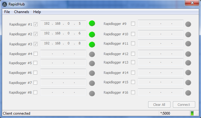
Using RapidHub with RapidVU


The Rapidlogger Utility is a program that can be run on a PC and allows the user to make changes to the Rapidlogger setup and configuration. It is not used in normal operation but only when there is a need to reconfigure some aspect of the Rapidlogger setup. This program has to be run on a PC that is on the same Ethernet network as the Rapidlogger Unit. It can be used to configure variables and system settings on the Rapidlogger unit.
To begin using the utility, click the button labeled “Find Rapidlogger”, after entering the unit’s IP address. If the correct IP address is entered then the presence of the unit at that address is confirmed by the software. Click “Read All from Unit” will open a screen on the right that shows the “Variables Defined”

Changing System Settings
To begin changing system settings, click the button labeled “System Setup” to access the System Setup dialogue. In order to begin changing settings, the unit’s current settings must be retrieved by clicking the button labeled “Read from Unit” button. Note that the dialog updates to reflect the Rapidlogger’s current settings.
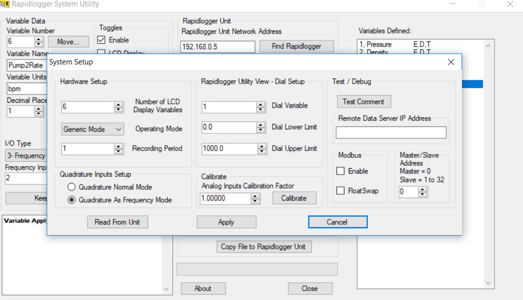
The options available from this dialogue are:
Number of LCD Display Variables – Choose how many variables the Rapidlogger unit will display on its LCD front panel.
Operating Mode – Change the Rapidlogger’s operating mode between Cement Pump, Slickline unit, N2 Pump, Coiled Tubing, Fracturing Pump, Simulate Cement, Simulate Slickline, Simulate CT, InRock, Simulate InRock, Generic Mode.
Recording Period – Set the frequency at which the Rapidlogger writes data to its job file. The options are data recording every 1, 5, 10, and 60 seconds.
Dial Variable – Choose the variable that will be displayed on the analog dial in the RapidVu program.
Dial Lower/Upper Limit – Set the range that the RapidVu dial will cover.
Analog Inputs Calibration Factor – Set the calibration multiplier for the Rapidlogger’s analog inputs. This option should be used with care. In order to recalibrate the analog inputs on a Rapidlogger Unit a precision calibrated current source is required. To prevent unintentional re-calibrations this option has have no effect unless the calibration mode is explicitly enabled on the Rapidlogger unit from the front panel.
The configuration of the two quadrature inputs on the Rapidlogger unit can be modified based on the application. In the normal mode these inputs are used to read the quadrature (A and B channels) from a quadrature or depth encoder. However, by checking the option "Quadrature as Frequency mode" these two quadrature inputs can also be used as two high-speed frequency inputs. This is useful for interfacing to devices such a micro-motion and Endress-Hauser densitometers and flow computer.
The other settings on this page pertain to Modbus communication and are discussed in more detail in the Modbus section.
Creating and Configuring Variables
All of the Rapidlogger data is based on calculations performed on input data. The results of the calculations are stored in the system variables. The settings of the input variables can be viewed and edited from the front panel and by using the PC based Rapidlogger Utility.
From the main screen, the following options for variable configuration are available:
Read One / Read All From Unit – These buttons control the loading of variables from the Rapidlogger. Typically, the Read All From Unit button is clicked before making any changes, as this allows the user to retrieve and review the configuration of all variables on the Rapidlogger from within the Rapidlogger Utility.
Write One / Write All To Unit – These buttons allow new variable setups to be exported to the Rapidlogger unit. Typically, each variable will be written one at a time as it is configured, although if the user is confident in their setup, all variables may be written at one time. Note that it may take several seconds for the unit’s front panel to reflect a change in the variable setup.
Sync Time – Updates the Rapidlogger’s internal clock to reflect the time on the PC running the Rapidlogger utility.
Write Vars File – Save the current variable configuration to a location on the PC running the Rapidlogger utility. The vars file can be used to save a complex setup for later use or back up the current variable configuration. Note that writing the current configuration to a vars file does not affect the Rapidlogger unit in any way.
Read Vars File – Load a variable setup from a previously-written vars file. Note that reading a vars file does not affect the Rapidlogger unit in any way – the variables must still be written to the unit.
Variable Number – Controls which variable is currently being edited.
Variable Name – Sets the name that identifies the variable on the Rapidlogger front panel and in the RapidVu program.
Variable Units – Determines the units (lbs, bpm, etc.) that the current variable is measured in. Note that the units are a label only – the Rapidlogger unit does not automatically perform the any calculations to convert sensor data from one unit system to another. Those calculations must be set up manually using the Multiplier and Offset options.
Decimal Places – Controls how many decimal places are displayed on the Rapidlogger front panel and the RapidVu program. Note that this setting does NOT affect the precision with which data is recorded and calculated.
Input Type – Choose what type of input this variable accepts. Most variables will be Analog, Frequency, or Frequency Total. The choice of variable type depends on the physical sensor that is being used, and affects the remaining options displayed in the Rapidlogger Utility. Other more advanced, or computed variable types are also available.
Analog Variables
Input Number – Choose which analog input channel this variable will use.
Multiplier – Change how the analog input is scaled to correspond to a certain reading in the chosen units.
Offset – Change the shift applied to analog input to correspond to a certain reading in the chosen units.
Frequency and Frequency Count Variables
Input Number – Choose which frequency input channel this variable will use. Typically, both a Frequency variable and a Frequency Count variable will be assigned to the same channel.
Multiplier – Change how the variable is scaled into the chosen units. Note that the multiplier will typically be off by a factor of 60 between a Frequency variable and its associated Frequency Count variable.
Offset – For Frequency type variables, this will almost always be 0.
While the utmost care has been taken in creation of the variable setup and configuration program it is possible to improperly setup the unit causing data to be incorrectly recorded and displayed. Note that this can be avoided by using the factory supplied setup files and making modifications to the calibration coefficients only as defined in the manual.
The IP Setup Utility needs to be run as administrator to function properly. This can be done by right-clicking on the application and selecting “Run as administrator”. The following popup will appear. Select Yes to continue.

Once the application is open select the network interface that is physically connected to the Rapidlogger device. There is usually both a wireless and local area network option as shown below.

Enter in the IP address To Add. This step will not interfere with the current IP address or change the network settings. Select Add IP.
« Previous · Contents · Next »