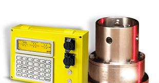
This section describes the use and setup of various types of sensors with the Rapidlogger system. The example calculations are meant for advanced users that have a good understanding of sensor setup and associated calculations. If there is any doubt please contact the factory for support on calculating the scale and offset factors for a specific type of sensor.
Pressure Transducer
Pressure is measured by means of a pressure transducer. In general, two types of pressure transducers are used in the oilfield: Hammer union type and threaded type. Both type of pressure transducers are analog sensors. Their output can be in the form of a current, a voltage or a millivolt signal. In all cases the analog output is proportional to the pressure that is applied to the pressure transducer. The output of a current type pressure transducer ranges from 4 to 20 milliamperes. These are the most common type of pressure transducers used in the oilfield and are sometimes called current loop, 4-20mA or milliampere sensors, these sensors can be directly connected to one of the milliampere inputs of the Rapidlogger. The output of a voltage type pressure sensor can range from 0-10Volts and this type of sensor can be attached to a Rapidlogger unit's analog input if they have been configured at the factory for Voltage input. A millivolt type pressure sensor can only be connected to the Rapidlogger analog inputs via a signal conditioner or current amplifier.
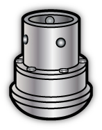
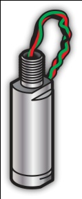
Analog sensors such as pressure transducers can be interfaced to one of the system's four high resolution analog inputs. All four analog inputs support 4-20mA signal inputs and both 2 and 3 wire sensors. The scale and offset values for a 15,000 psi pressure transducer can be calculated as follows.
Rapidlogger mA input setup
0-20mA full range = 65535 (A/D counts)
4-20mA scaled range = 52428 (A/D counts)
0-4mA scaled range = 13107 (A/D counts)
Scale Factor = 15000 (psi) / 52428 (AtoD counts) = 0.2861066 (psi/count)
Offset Value = 0.2861066 x 13107 = -3750 (psi)
Proximity Sensors
Pump stroke sensors are proximity switches that sense the rotation of some moving part of a pump. Both 2 and 3 wire type proximity switches ranging from 12-24V can be interfaced to the Rapidlogger. Proximity sensors or stroke counters as they are sometimes called can be one three common types. The most commonly used type of proximity sensor is in inductive proximity switch that generates a signal every time a piece of metal is within range. Other type of sensors can be a reed switch that causes a switch closure every time it is exposed to a magnet. The Rapidlogger can accommodate most types of DC proximity switches (Pulse type, open collector type and dry contact/switch closure type).
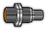
Software setup for all of these sensors would be the same but they may have to be wired differently based on their manufacturer’s documentation. Two of the Rapidlogger frequency inputs (F1, and F2) are meant strictly for proximity switches and can accommodate both square wave and sinusoidal type inputs from -24 to 24V. The other two frequency inputs (Q1A, and Q2A) are shared between the frequency input and quadrature inputs and can only accommodate positive DC square wave inputs (such as the ones generated by the majority of proximity sensors. The usage of these two inputs (Q1A, and Q2A) can be configured from the front panel to be for frequency or Quadrature. Each of the four frequency inputs is automatically totalized by the system and the totals are available to be displayed and can be recorded. The conversion factor for a pump equipped with a 2000 pulse per barrel proximity switch can be calculated as follows.
Rapidlogger total counts input setup
Pulses per barrel = 2000 pulses/barrel
Scale Factor = 1 / 2000 pulses/barrel
Offset Value = 0 barrels
Rapidlogger rate setup (for barrels / minute)
Internal rate time base = 1 seconds
External rate time base = 1 minute = 60 seconds
Pulses per barrel = 2000 pulses / barrel
Internal to external rate conversion = 60/1 = 60
Scale Factor = 1 / 2000 x 60 = 0.03
Offset Value = 0 barrels / minute
Depth Encoder
A depth encoder is used on slickline, electric line, and coiled tubing operations to measure the length or depth of wire or pipe in the hole. This is usually done by running a friction wheel on the wire or pipe. The friction wheel is connected to the shaft of the depth encoder. A depth encoder is shown below along with one with a slickline depth friction wheel adapter attached.
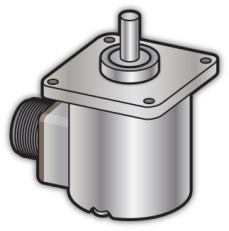
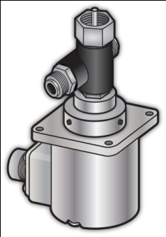
The output of a depth encoder is in the form of two sets of pulse signals (usually labeled A and B signals) that are 90 degrees out of phase with each other. These are called quadrature pulses and the encoders are called quadrature encoders. The output pulses from a depth encoder are usually 5Volt however some types of depth encoders have 12 volt output pulses. The Rapidlogger can be interfaced with up to two quadrature encoders with output pulses ranging from 5 to 24 Volts. In order to calculate the scaling factor of a depth encoder some information about its mounting scheme is also required. A depth encoder attached to the friction wheel on a slickline unit is shown below.
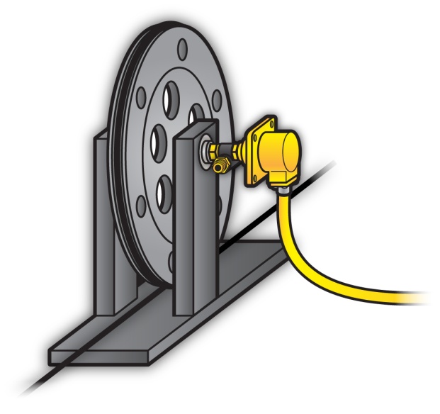
In the previous diagram the depth encoder is connected to the friction wheel through a 1:1 ratio. So for each turn of the encoder slickline equal to one circumference of the wheel will pass through. Different depth encoders can have different number of pulses per revolution. The scale factor for a 300 pulse/revolution depth encoder mounted on a 2 foot circumference wheel can be calculated as follows.
Rapidlogger total quadrature input setup
Pulses per revolution = 300 (pulses / revolution)
Pulses per foot = 300 (pulses) / 2 (ft) = 150 (pulses per foot)
Scale Factor = 1 / 150 (feet / pulse) = 0.0066667
Offset Value = 0 (feet)
Rapidlogger quadrature rate setup
Internal rate time base = 1 seconds
External rate time base = 1 minute = 60 seconds
Internal to external rate conversion = 60/1 = 60
Scale Factor = 1 / 150 x 60 (feet / pulse/minute) = .4000
Offset Value = 0 (feet/minute)
If the wheel diameter is used to calculate the wheel circumference rather than a calibration run in the shop or yard, then the diameter of the slickline should also be taken into account in the calculation of the circumference.
Rapidlogger slickline friction wheel circumference calculation
Diameter of the wheel at bottom of slickline groove in wheel = 1.0 ft
Diameter of the slickline = 0.125 inch = 0.0104167 ft
Effective diameter of the wheel = 1 ft +2 x (0.0104167 / 2) ft
Effective diameter of the wheel = 1.0104167ft
Circumference of wheel = Pi x diameter = x diameter = 3.1743176
Rapidlogger total quadrature input setup
Internal to external rate conversion = 60/1 = 60
Pulses per revolution = 300 (pulses / revolution)
Pulses per foot = 300 / 3.1743176 = 94.5085 (pulses per foot)
Scale Factor = 1 / 94.5085 (feet / pulse) = 0.01058106
Offset Value = 0 (feet/minute)
Rapidlogger quadrature rate setup
Scale Factor = 1 / 94.5085 x 60 (feet / pulse/minute) = 0.63486352
Offset Value = 0 (feet/minute)
Load Cell
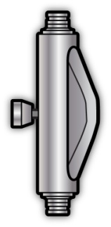
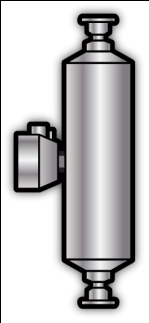
Tension and compression on slickline, wireline and coiled tubing units are measured by means of load cells. Load cells come in many different shapes and sizes. Two different types of load cells are shown below. The output of load cells can be in the form of a current, a voltage or a millivolt signal. In all cases, the analog output is proportional to the tension or compression that is applied to the load cell.
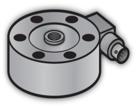
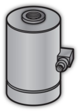
An analog load cell can be connected to any of the four milliamp inputs of the Rapidlogger. The scale and offset values for a 50000 lbs compression only load cell can be calculated as follows.
Rapidlogger mA input setup
0-20mA full range = 65535 (A/D counts)
4-20mA scaled range = 52428 (A/D counts)
0-4mA scaled range = 13107 (A/D counts)
Scale Factor = 50000 (lbs) / 52428 (AtoD counts) = 0.95369(lbs/count)
Offset Value = 0.95369 x 13107 = -12500 (lbs)
The scale and offset values for a 50000 lbs tension/compression load cell can be calculated as follows.
Rapidlogger mA input setup
0-20mA full range = 65535 (A/D counts)
4-20mA scaled range = 52428 (A/D counts)
Zero for a tension compression cell would be at 12mA or 39321 counts
Scale Factor = (50000+50000) (lbs) / 52428 (counts) = 1.907378 (lbs/count)
Offset Value = 0.1907378 x 39321 = -75000 (lbs)
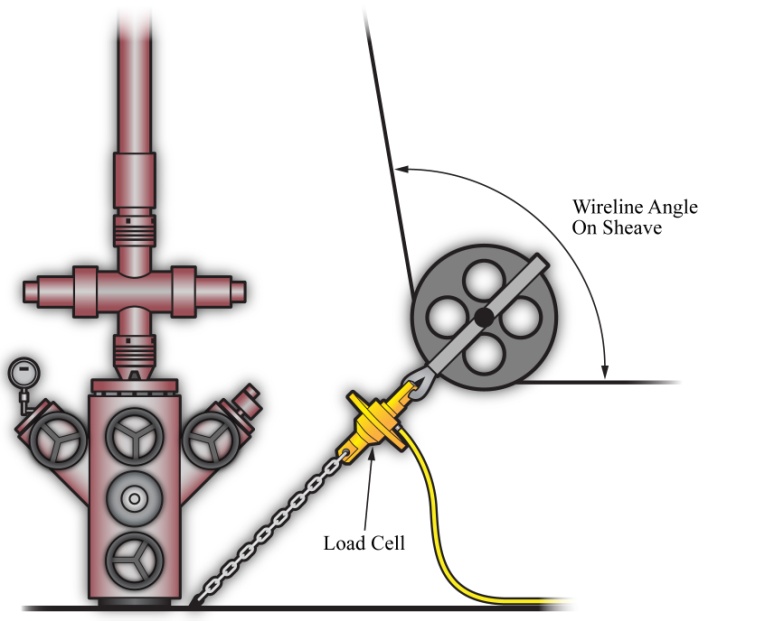
For slickline and electric line work the load cell is often attached to the bottom sheave at the wellhead. In such an installation the load cell sees a different load than the tension in the line. This changes the calculation for the scale factor and the offset of the load cell. This type of an installation is shown earlier in this section. If the wireline angle over the bottom sheave is 90 degrees then the scale and offset values for a 5000 lbs tension load cell installed on a wireline or slickline unit on the sheave shackle can be calculated as follows.
Rapidlogger mA input setup for sheave wheel attachment
0-20mA full range = 65535 (A/D counts)
4-20mA scaled range = 52428 (A/D counts)
0-4mA scaled range = 13107 (A/D counts)
Wireline Angle on sheave = 90 degrees
Sheave factor = 2 x cos(90 / 2) degrees = 2 x 0.707106 = 1.4142135
Scale Factor = Loadcell capacity / Sheave factor / 4-20mA scaled range
Scale Factor = 5000 / 1.4142135 / 52428 = 0.0674359866 (lbs/count)
Offset Value = 0.0674359866 x 13107 = -883.883 (lbs)
The wireline angle over the sheave is not always 90 degrees. In the following calculation example, the scale factor and offset for a 2000 lbs load cell installed on a sheave with a wireline angle of 95 degrees is calculated.
Rapidlogger mA input setup for sheave wheel attachment
0-20mA full range = 65535 (A/D counts)
4-20mA scaled range = 52428 (A/D counts)
0-4mA scaled range = 13107 (A/D counts)
Wireline Angle on sheave = 95 degrees
Sheave factor = 2 x cos(95 / 2) degrees = 2 x 0.6755902 = 1.3511804152
Scale Factor = Load cell capacity / Sheave factor / 4-20mA scaled range
Scale Factor = 2000 / 1.3511804152 / 52428 = 0.0282327621 (lbs/count)
Offset Value = 0.0282327621 x 13107 = -370.04 (lbs)
Coriolis Flowmeter and Densitometer
Many modern cement units are equipped with a Coriolis-type densitometer (Micro Motion, Endress+Hauser, etc.). These densitometers can measure the flow-rate, volume, and density of the treatment fluid. The output from the densitometers is generally in the form of an analog output for density and a frequency output for the flow rate. These signals can be interfaced to the Rapidlogger unit and the data can be displayed and recorded. The milliampere outputs from the flowmeter transmitter unit can be connected to one of the milliampere inputs, and the frequency outputs from the flowmeter can be connected to one of the frequency inputs of the Rapidlogger. The flow and density meters from Micro Motion and Endress+Hauser allow the scaling of the output signal. These scale factors are configurable on the output transmitters made by the manufacturers. This is usually accomplished by a PC based setup program that is provided by the manufacturer of the flowmeter. The output scale factor must be known in order to properly interface the flow and density meters to the Rapidlogger.
Once these scale factors are known, the analog and frequency scale and offset settings of the relevant Rapidlogger inputs can be calculated as shown in the previous sections. Generally, the flowmeter output the density on a milliamp output and the flow rate is transmitted on a frequency output from the flowmeter transmitter. Contact the factory for more support on interfacing flowmeters to the Rapidlogger system.
Shutdown Relay for Over-pressure conditions
Many modern pumping units are equipped with a pump shutdown system. These systems normally can operate on a pneumatic, electric or hydraulic circuit. In case it is desired that the Rapidlogger System shutdown the pump in case of an overpressure condition then the output relay can be configured as follows.
The control output wiring on the Rapidlogger is normally connected to output Relay 7. This can be programmed using the Rapidlogger System Utility as follows:
Rapidlogger Relay output setup
I/O Type = Relay Output
Input number = 7
Limit Value = 5000 (where 5000 is the desired overpressure shutdown pressure)
Compare Variable = 1 (where variable 1 is the pump pressure)
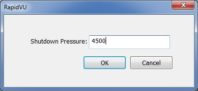
The pressure shutdown can be programmed in the RapidVU software as follows:
Select the Shutdown Pressure button and a popup will appear.

Enter the desired shutdown pressure (default: 14900.00 psi). Select OK.
The SD Memory card (5) installed in the Rapidlogger unit records all job data when it is powered on. The operator does not need to do anything to start the job recording, other than turning the unit on. In normal use the data is retrieved from the SD Memory card via Ethernet link using the supplied PC programs “RapidVu” or the “Rapidlogger System Utility”. As more and more data is recorded on the SD Memory card it starts getting full. It is strongly recommended that the SD Memory card be erased or formatted every few weeks to prevent data corruption. This can be done by using the “Rapidlogger System Utility” program or from the front panel keypad of the (Press F6, F6, F6, F5). Please make sure all old job data has been transferred from the SD Card to the PC.
WARNING: The SD card on the Rapidlogger can be corrupted by repeated improper power shutdowns and fluctuations. The user should download all important job data after every job. The SD card should be formatted / erased either from the front panel or by using the RapidVu program every few jobs (10 - 15 jobs) after they have been downloaded.
The various components of the Rapidlogger system are shown in the diagram below.
111155667788101099332211441212
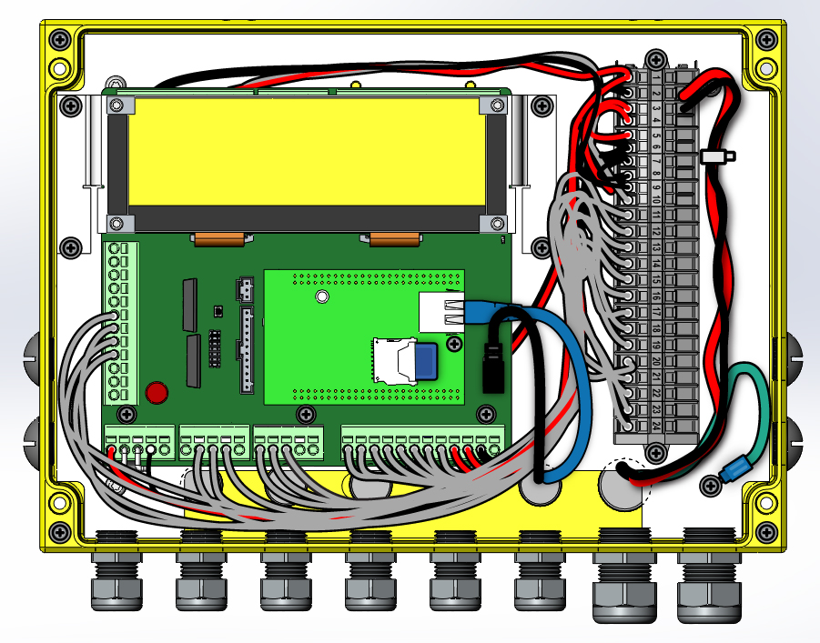
1) LCD screen
2) Main board
3) Power connector
4) Serial port connector
5) SD Card
6) SD Card connector
7) Ethernet Connector
8) Grounding connector
9) Field Replaceable 1 Amp Fuse
10) Wiring terminal
11) Mounting plate
12) CPU Module
When using the Rapidlogger system with the supplied Rapidlogger WiFi Access Point connection is simple. Simply connect your Computer or Laptop to the WiFi access point named Rapidlogger. All network settings will be automatically configured.
The Rapidlogger is equipped with a weatherproof Ethernet connector. If a cable is installed in this connector and connected to a network port, the Rapidlogger can communicate with a PC computer. Most Ethernet cables that are used are wired straight through and are meant to attach a device to an Ethernet Hub or Switch. This is the type of cable that is installed on the Rapidlogger. The second type of Ethernet cables that are used are wired in a crossover manner and are meant to connect two devices to each other without the need for a hub. A short crossover patch is supplied with the Rapidlogger and can be installed in between the Ethernet socket (7) and cable connector.
Thus, if the installation requires the Rapidlogger to communicate with a PC through a Hub/Switch as in the majority of the cases, then the Ethernet cable should be used without any changes. If, however the installation requires the Rapidlogger to communicate with a PC without a Hub/Switch then the crossover patch should be installed inside the Rapidlogger unit.
The second part of communicating with a PC is setting up of the correct IP address, gateway address and network mask. There are two types of address setup mechanisms, automatic/dynamic/DHCP and static. The Rapidlogger unit uses static IP addresses. The current IP address and gateway address setup in the unit is displayed on the screen on the bottom left and bottom right of the screen for a few seconds after the unit is powered up. Both or these are numbers are a sequence of four three digit numbers of the form (192.168.000.005). In order for the Rapidlogger to communicate properly with a PC over the Ethernet connection, the PC and Rapidlogger should have compatible IP addresses that are within the same subnet. If the user is unfamiliar with IP addresses then it is recommended that they use the following.
PC / Laptop IP: 192.168.000.001 Gateway: 192.168.000.001 Netmask: 255.255.255.000
Rapidlogger IP: 192.168.000.005 Gateway: 192.168.000.001 Netmask: 255.255.255.000
IP settings on a PC are done from the Windows control panel in the IP setting field within the properties of the LAN Connection Dialog box. On the Rapidlogger these settings are done from the front panel keypad. Press F6, F6, F1 and then enter the IP address, Gateway and Netmask when prompted on the screen. Perform a power cycle to verify and activate the IP address from the LCD screen. The default IP address of 192.168.000.005 is setup in the system at the factory. This is also the IP address that the system goes back to whenever a factory reset is done. Advanced users should select and utilize the IP addresses appropriate for their network.
Once the IP addresses are setup then the PC and the Rapidlogger are able to communicate with each other. Proper communication can be verified by performing a PING from the PC to the Rapidlogger IP address. Do note that some PC firewall programs block Ethernet communication that they are not familiar with. If you have such a firewall running on your PC then you may either need to disable it or specifically setup it up to allow full two way communication to the Rapidlogger IP Address.
The Rapidlogger Unit has a built-in diagnostics mode in which the raw sensor inputs can be viewed to ease troubleshooting. The diagnostics mode for analog sensors can be accessed from the front panel keypad (Press F6, F6, F5, F1, F1). The diagnostics mode for frequency sensors can be accessed from the front panel keypad (Press F6, F6, F5, F2). In each case a screen appears on the LCD that displays the various sensor values.
All of the Rapidlogger data is based on calculations performed on input data. The results of the calculations are stored in the system variables. The settings of the input variables can be viewed and edited from the front panel and by using the PC program Rapidlogger Utility.
In order to view a system variable, select the view option (Press F6, F6, F4, F3) and then enter the variable number to view. To edit a system variable, select the view option (Press F6, F6, F4, F4) and then enter the variable number to edit. The system will prompt you with the current value of each of the settings for that particular variable and then allow you to enter a new value. For any values that need to remain unchanged press F6 and the system will skip to the next value. Editing system variables is a feature that should only be done by advanced users and then too it should be done by using the Rapidlogger Utility.
The Rapidlogger unit is capable of communicating with other third party devices HMIs, SCADA, systems, and PLCs using Modbus. The Modbus protocol is a messaging structure, widely used to establish master-slave communication between intelligent devices. A Modbus message sent from a master to a slave contains the address of the slave, the 'command' (e.g. 'read register' or 'write register'), the data, and a check sum. Since the Modbus protocol is just a messaging structure, it is independent of the underlying physical layer. On the Rapidlogger Unit it is implemented in Ethernet and it used the Modbus-TCP/IP protocol. The Rapidlogger operates in Modbus slave mode. Both Read and Write to Modbus Holding registers are allowed.
In order to enable modbus, use the Rapidlogger Utility and on the System Setup dialog box enable Modbus and select a slave address.

Restart the Rapidlogger Unit. All variables defined on the Rapidlogger will now be automatically available via Modbus. So Rapidlogger Variable #1 will be available as Modbus Holding Register 1, as a 32 bit floating point value in Big-endian format. Rapidlogger Variable #2 will be available as Modbus Holding Register 3, as a 32 bit floating point value. Rapidlogger Variable #3 will be available as Modbus Holding Register 5 and so on.
If there is a need to write a variable to the Rapidlogger using Modbus then the first step is to create a Modbus Receive type variable on the Rapidlogger as follows.

Now if a Modbus Master device writes a 32 bit floating point number to Modbus Register # 23 then the Rapidlogger Variable 12 will be updated with this value.
Note that either Modbus or WITS0 protocol can be enabled at one time. All Modbus polling on the Rapidlogger is limited to a 1Hz acquisition rate.
The Rapidlogger unit is capable of communicating with other third party devices HMIs, SCADA, systems, and PLCs using WITS. The WITS or Wellsite Information Transfer Standard communication protocol is used to transfer drilling and geology data between systems at a wellsite. This protocol serially streams data by using a pre-defined record with channels and values. The pre-defined record used with the Rapidlogger unit is a subset of the WITS0 or WITS level 0 record.
WITS0 Network Output Screen can be reached through Data menu
WITS from Network


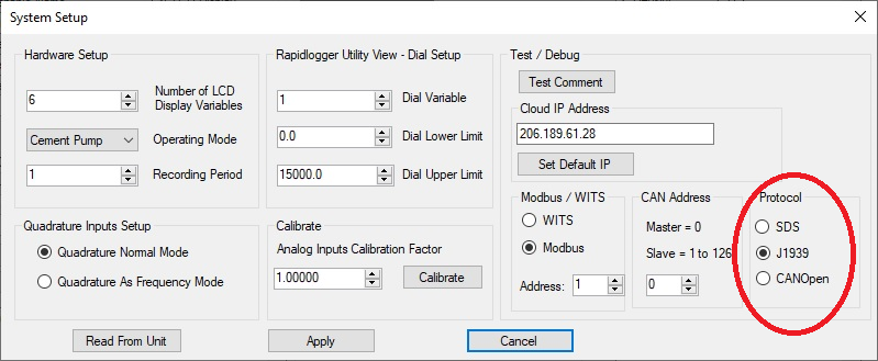
The Rapidlogger unit supports communication over the J1939 protocol. This allows it to get data from engines and transmissions that have J1939 capable ECUs. In order to setup the use of J1939 data from the engine or transmission, three steps need to be completed.
The first step is to enable the J1939 protocol in the Rapidlogger System by using the Rapidlogger Utility. The protocol setup can be done in system setup dialog box as shown below
The second step is to place a “_j1939cfg.csv” file in the Rapidlogger System sd-card. This file must be placed in the root directory of the sd-card. This file can be downloaded from the Rapidlogger Systems website in the downloads area. This file instructs the Rapidlogger System to create temporary variables numbered 71 through 85 in the system memory and then fill them with CAN bus J1939 data as it comes in from the J1939 devices. A sample copy of the file is shown below.
# J1939 Rapidlogger System Configuration file,,,,,,,,,,,# File needs to be placed in root directory of SD card on Rapidlogger System# Column A is DAQ Var Number 1-100,,,,,,,,,,,# Column B is J1939 PGN (parameter group number); non-standard PGNs: # Column C is the cyclic request/write time if request column is set to Y# Column D is 'request': N or Y,,,,,,,,,,,# Column E is the address: N= no, E= engine, T=transmission, A= ABS, S= Summary from multiple# Column F is the map: start byte, bit and length: byte.bit.len",,,,,,,,,,,# Column G is the Read/Write Direction, Value 'R' OR 'W' means J1939 read or write # Column H is a J1939 gain# Column I is a J1939 offset# Column J is a J1939 label# Column K is a comment,#70,61444,0,n,N,0,R,0.0000000000,0.00,Custom,Custom Parameter,71,61444,0,n,N,4.1.16,R,0.1250000000,0.00,RPM,Engine RPM ,72,65253,2000,Y,E,1.1.32,R,0.0500000000,0.00,hr,Engine Hrs ,73,65271,0,n,N,7.1.16,R,0.0500000000,0.00,V,Batt.Poten.Voltage,74,61443,0,n,N,3.1.8,R,1.0000000000,0.00,%,Engine Load at RPM,75,65262,0,n,N,1.1.8,R,1.0000000000,-40.00,degC,Coolant temperature,76,65263,0,n,N,4.1.8,R,4.0000000000,0.00,kPa,Engine Oil Pressure,77,65266,0,n,N,1.1.16,R,0.0500000000,0.00,L/h,Fuel Rate ,78,61443,0,n,N,2.1.8,R,0.4000000000,0.00,%,Accel.Pedal Position,79,65270,0,n,N,3.1.8,R,1.0000000000,-40.00,degC,Intake manif.temperature,80,65266,0,n,N,3.1.16,R,0.0019531250,0.00,km/kg,Inst.Fuel Economy ,81,65272,0,n,N,4.1.8,R,16.0000000000,0.00,kPa,Transm. Oil Pressure,82,65272,0,n,N,5.1.16,R,0.0312500000,-273.00,degC,Transm. Oil Temperature,83,65226,0,n,S,1.2.1,R,0.0000000000,0.00,x,RED lamp: JMAP byte.bit.len n 84,65226,0,n,S,2.2.1,R,0.0000000000,0.00,x,AMBER lamp,85,61441,0,n,N,1.1.2,R,1.0000000000,0.00,x,ASR Eng.CtrlAct - at least one PGN required# 1, 99999,1000,n,N,1.1.8,W,0.0085000000,0.00,psi,RL's pressure to broadcast# J1939 Rapidlogger System Configuration file,,,,,,,,,,,# File needs to be placed in root directory of SD card on Rapidlogger System# Column A is DAQ Var Number 1-100,,,,,,,,,,,# Column B is J1939 PGN (parameter group number); non-standard PGNs: # Column C is the cyclic request/write time if request column is set to Y# Column D is 'request': N or Y,,,,,,,,,,,# Column E is the address: N= no, E= engine, T=transmission, A= ABS, S= Summary from multiple# Column F is the map: start byte, bit and length: byte.bit.len",,,,,,,,,,,# Column G is the Read/Write Direction, Value 'R' OR 'W' means J1939 read or write # Column H is a J1939 gain# Column I is a J1939 offset# Column J is a J1939 label# Column K is a comment,#70,61444,0,n,N,0,R,0.0000000000,0.00,Custom,Custom Parameter,71,61444,0,n,N,4.1.16,R,0.1250000000,0.00,RPM,Engine RPM ,72,65253,2000,Y,E,1.1.32,R,0.0500000000,0.00,hr,Engine Hrs ,73,65271,0,n,N,7.1.16,R,0.0500000000,0.00,V,Batt.Poten.Voltage,74,61443,0,n,N,3.1.8,R,1.0000000000,0.00,%,Engine Load at RPM,75,65262,0,n,N,1.1.8,R,1.0000000000,-40.00,degC,Coolant temperature,76,65263,0,n,N,4.1.8,R,4.0000000000,0.00,kPa,Engine Oil Pressure,77,65266,0,n,N,1.1.16,R,0.0500000000,0.00,L/h,Fuel Rate ,78,61443,0,n,N,2.1.8,R,0.4000000000,0.00,%,Accel.Pedal Position,79,65270,0,n,N,3.1.8,R,1.0000000000,-40.00,degC,Intake manif.temperature,80,65266,0,n,N,3.1.16,R,0.0019531250,0.00,km/kg,Inst.Fuel Economy ,81,65272,0,n,N,4.1.8,R,16.0000000000,0.00,kPa,Transm. Oil Pressure,82,65272,0,n,N,5.1.16,R,0.0312500000,-273.00,degC,Transm. Oil Temperature,83,65226,0,n,S,1.2.1,R,0.0000000000,0.00,x,RED lamp: JMAP byte.bit.len n 84,65226,0,n,S,2.2.1,R,0.0000000000,0.00,x,AMBER lamp,85,61441,0,n,N,1.1.2,R,1.0000000000,0.00,x,ASR Eng.CtrlAct - at least one PGN required# 1, 99999,1000,n,N,1.1.8,W,0.0085000000,0.00,psi,RL's pressure to broadcast
The third step is to configure the Rapidlogger Variables as needed to utilize the J1939 data in the job recording or job report file. For example if one wants to setup Variable 71 to show the engine rpm they would configure the variable 71 as follows.
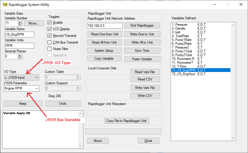
This complete the J1939 software and configuration setup. A reboot of the Rapidlogger System is required after this to enable all of the setting correctly. CAN bus data connections are to be made to the Rapidlogger Main board terminal block J8-1 J8-2 and J8-3. This terminal block is located below the LCD panel of the Rapidlogger and is moderately difficult to access.
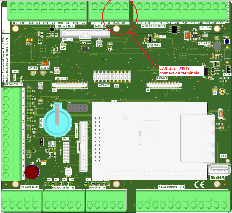
A CAN bus termination resistor may or may not be required depending on weather or not a termination resistors are part of the CAN bus wiring that is used for connecting the Rapidlogger to the Engine/Transmission.
Data from the Rapidlogger Unit can be sent to a cloud server and accessed in realtime at a remote location. The cloud server address can be set up using the Rapidlogger Utility as follows
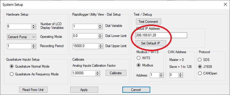
The default Clould Server IP address connects the Rapidlogger to the Rapidlogger Systems cloud server. If a clients has chosen to setup their own private cloud server they can enter the IP address of their server. Once this setup is complete then the next step is to connect the ethernet cable of the Rapidlogger Unit to a router or gateway that allows connectivity to the internet.
If using the Rapidlogger Cloud server go to the Rapidlogger Cloud server access page at the following link
http://www.rapidlogger.com/pages/RapidCloud.html
The following page will appear on your browser

Enter your company name and password. Company names and passwords are setup free of charge by contacting the Rapidlogger Systems support via email at support@rapidlogger.com.
Once on your company page on the Rapidlogger Cloud server the following appears on your browser

This page shows all of the Rapidlogger Units registered to the company. Clicking on “Detail” gives the live data in the browser.
Rapidlogger unit data sent to the cloud can also be accessed via the RapidVu program as follows
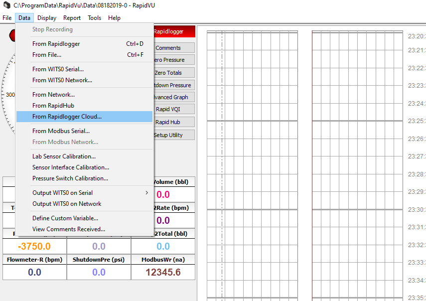
If one is using the Android or iPhone app then cloud data can be accessed as follows

This Wi-Fi access point will allow you to wirelessly communicate between your Rapidlogger system and computer. The Wi-Fi kit for the Rapidlogger system comes with a high-powered, long range 2.4 GHZ outdoor access point (AP) and an enclosed power supply as shown below.
The 3rd Generation Rapidlogger Access Point
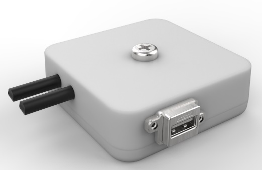
The 2nd Generation Rapidlogger Access Point

The 1st Generation Rapidlogger Access Point
1) Wi-Fi access point device
2) Wi-Fi power supply
3) Power in connector
4) Ethernet to Rapidlogger connector
5) Ethernet to access point device connector
Connecting the Access Point (AP)
Turn on the Rapidlogger Unit.
Click on the internet symbol located on the bottom right hand corner of your laptop screen. Switch your network to Rapidlogger (Rapidlogger Accesspoint).
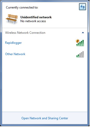
Click on the internet symbol again and click Open Network and Sharing Center.
Select Change adapter settings located on the left. Click the local area connection and under properties select Internet Protocol Version 4 (TCP/IPv4).

Switch the setting to obtain an IP address automatically.
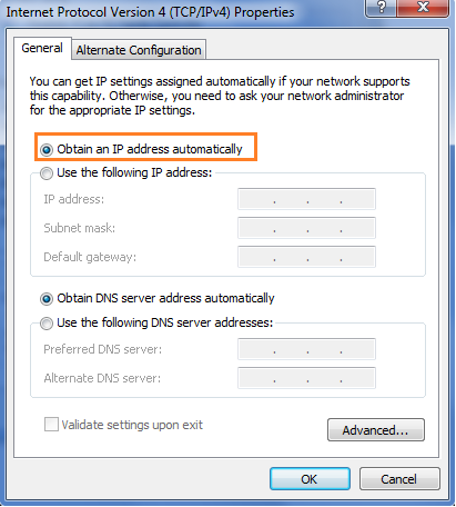
Click OK. And again Click OK.
To verify this setup open the RapidVU software and try to run by clicking Data > From Rapidlogger. If the Rapidlogger word and circle light up green, then you are connected.
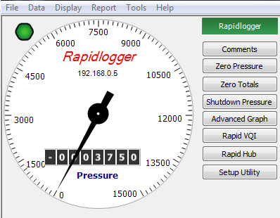
You should now able to communicate to the Rapidlogger system from your computer. The 2nd and 3rd Generation WiFi APs comes preinstalled in the Rapidlogger and does not require any installation.
The web page access will allow you to have read-only access to all the Rapidlogger files that have been saved to the Rapidlogger device SD card. Once a Rapidlogger file is saved to your PC this allows you to read the data using the RapidVU software.
On your PC that is connected via Ethernet to the Rapidlogger enter the IP address of the Rapidlogger device (default IP address: 192.168.0.5). In the address bar type ftp://192.168.0.5

The web page will appear and contain all the Rapidlogger files with the following information: file save date and time, size in bytes and name of the file in link form for read-only access.
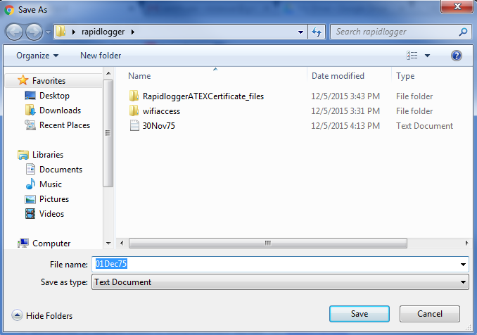
To save a Rapidlogger file right-click on the file and select Save link as…. The file name defaults to the same name shown on the web browser. Select the Save button after selecting the desired location to save the file.
Note: To read the data in this recently saved *.txt file refer to the instructions “To read data from a *.txt file:” in section 2.7 Using the RapidVU Program.
To view a file in the web browser, double-click on any available file. The file will appear with read-only access as shown below.

To return to the file list, click the back button in the web browser.
« Previous · Contents · Next »