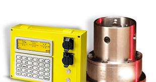
The installation of hazardous area ATEX certified equipment shall be done in accordance with the latest applicable edition of EN 60079-14. For overall installation details see installation drawing in Appendix A.
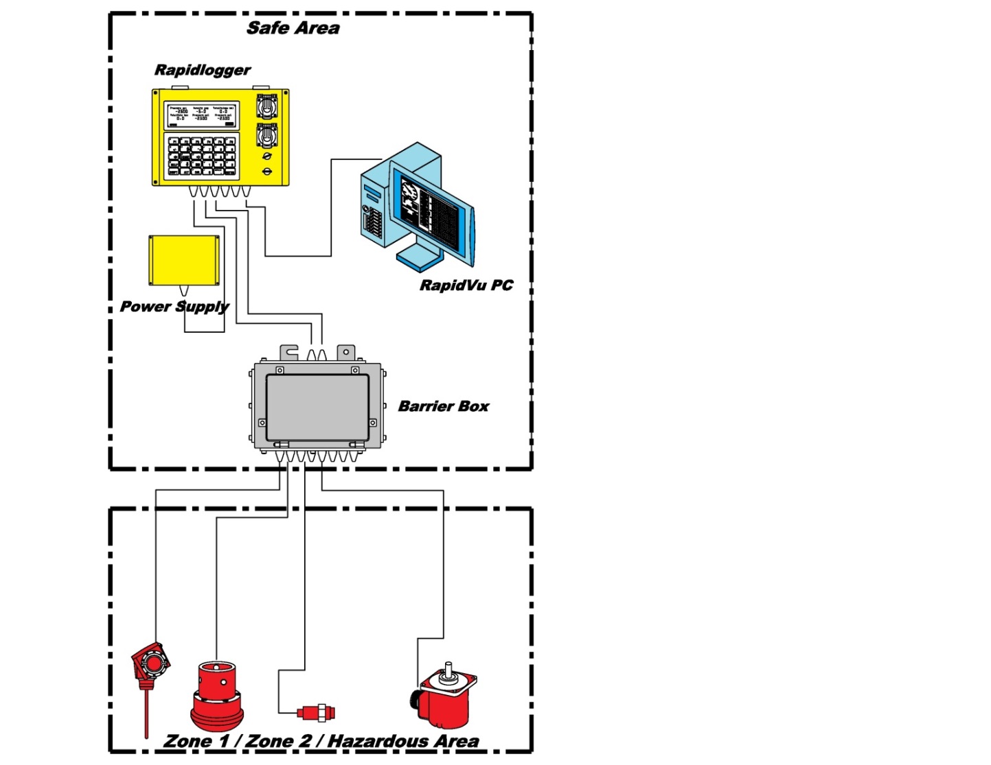
The summary illustration above shows that the installation of the Rapidlogger System in the hazardous areas involves installing certain components in the safe area and some components in the hazardous area. The installation of the ATEX certified Rapidlogger System can only be done by electrical installers that are properly certified to work in the specific area. These certifications are specific to the countries where the installation is taking place.
The Rapidlogger panel has been designed to be installed and used in harsh environments. The unit will operate well in direct sunlight, rain and sea water spray; however, protecting it from the elements will extend its life and maintain the appearance. Installation will vary slightly depending on whether the single box unit or the double boxed outdoor unit is being installed.
Installation of the double box unit
The double boxed Rapidlogger unit is the more common assembly that is supplied. This consists of metal Rapidlogger unit enclosed inside a larger polycarbonate box with a clear front. The secondary enclosure provides a very high degree of protection to the electronics in the unit from rain, dirt, physical damage, and pressure wash sprays. An illustration of this unit and a multi voltage power supply appears below.
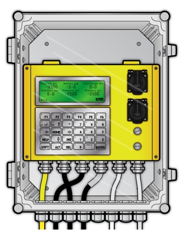

The first step in the installation is to identify an appropriate mounting location on the equipment to mount the Rapidlogger and the power supply. Next place the unit in the spot to be mounted and mark the location of the four mounting holes with a center punch or use the hole pattern drawing.
Make sure that the unit is level. Drill holes in the panel with a drill bit sized for ¼” clearance (9/32” would be appropriate). Next do the same for the holes for the power supply unit. Use the supplied (2” long 1/4"-20 size socket head) bolts and lock nuts to fasten the unit to the control panel. Do the same for the power supply unit. Next route the power and sensor cables as needed around the equipment and connect them to the power source and the sensors. All required cables come prewired to the unit generally only minimal wiring has to be performed.
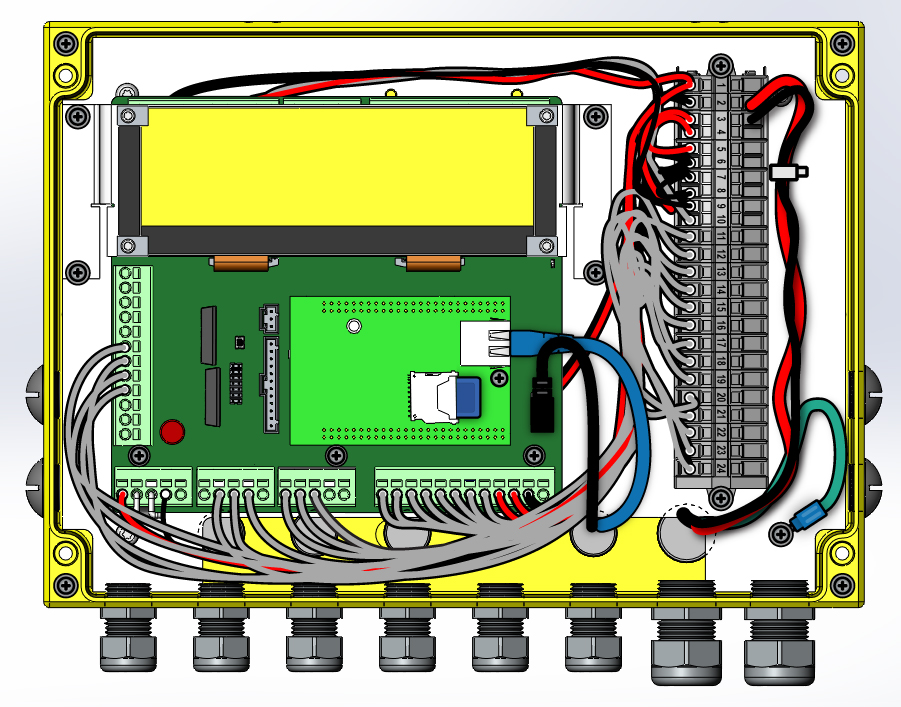
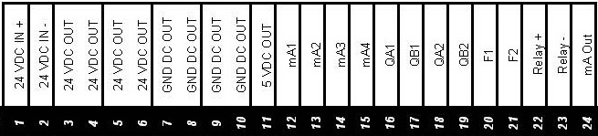
Wire Terminal Layout – Standard Unit
Installation of the Single boxed unit
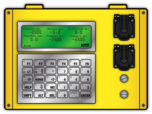
If installing a single boxed Rapidlogger unit follow these instruction and steps. An illustration of the regular unit appears below. The Rapidlogger Single box unit can be mounted in outdoor environments such as on the side of oilfield trucks and skids without any weather protection. However, in such applications the Rapidlogger unit lid should be kept tightly closed and the inside protected with a dry desiccant pouch.

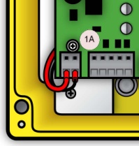
If you need to remove the hinged Rapidlogger lid from the back of unit to install then the keypad cable needs to be detached. This can be done by carefully detaching the keyboard cable from the unit lid by depressing the small locking tab (1) on the keypad connector and gently pulling and rocking the connector back and forth. The mounting holes (2) used to mount the unit to a control panel are visible once the lid has been opened.
112222


Find a place on the panel to mount the Rapidlogger panel. Place the unit in the area to be mounted and mark the location of the four mounting holes with a center punch or use the hole pattern drawing. Drill the holes in the panel with a 1/4"drill bit. If you want to route the cables using the rear cable exits on the Rapidlogger then you must drill holes to clear the cable and cord grips also. Thread the cables through the holes, and use the supplied (10-24 size) bolts and nuts to fasten the unit to the control panel.
Installation of the Rapidlogger Mini unit
If installing a Rapidlogger Mini unit follow these mounting holes
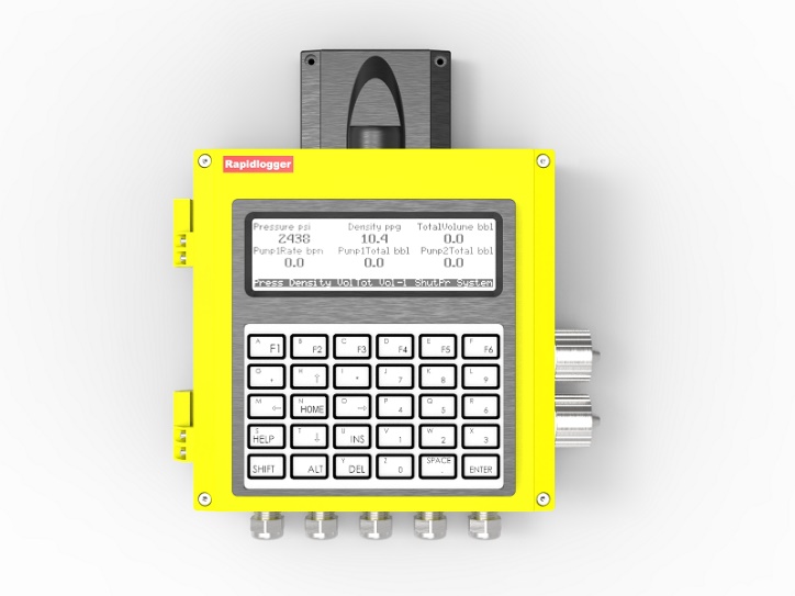

The Rapidlogger Mini can be mounted in outdoor environments such as on the side of oilfield trucks and skids without any weather protection. However, in such applications the Rapidlogger unit lid should be kept tightly closed and the inside protected with a dry desiccant pouch.
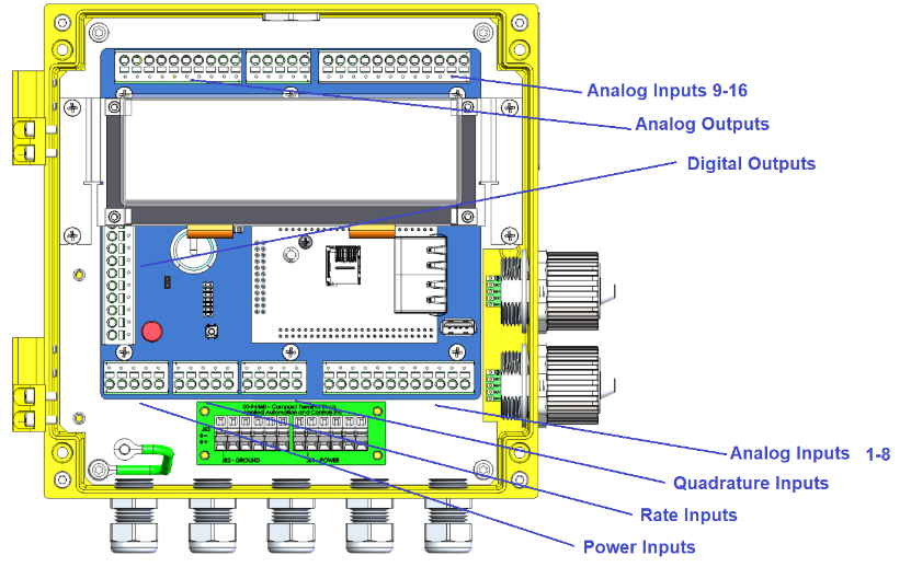
Wire Terminal Layout – Mini Unit
Installation of the Rapidlogger ExD unit
The Rapidlogger ExD unit is used for acquiring data in Hazardous Zone 1 and Zone 2 locations. It can be used as a standalone data If installing an Rapidlogger ExD unit. Use the following mounting holes.
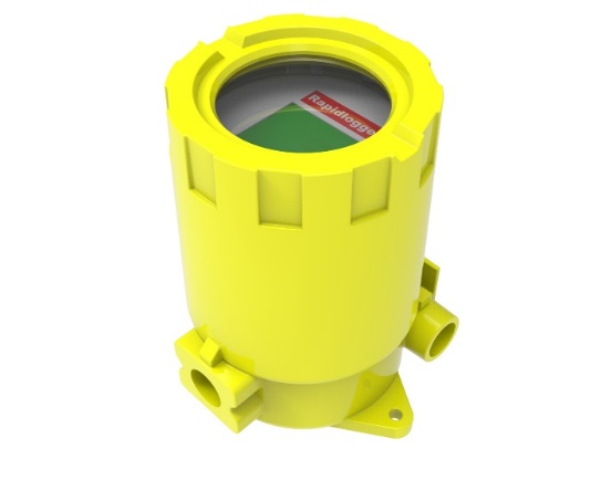
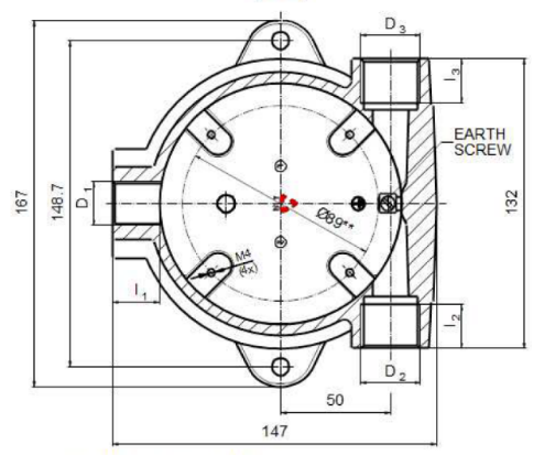
The Rapidlogger ExD can be mounted in outdoor environments such as near wellheads, CT injectors, and Mud tanks. However, in such applications the Rapidlogger ExD lid should be kept tightly closed and the inside protected with a dry desiccant pouch. Only armored cables can be used with the Rapidlogger ExD when it is installed in Hazardous areas.
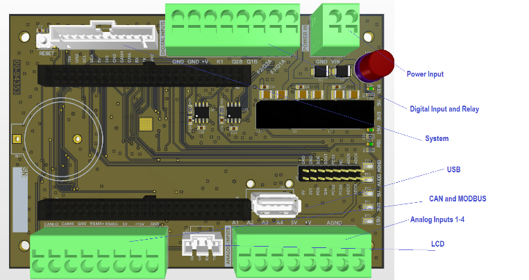
Wire Terminal Layout – ExD Unit
Installation of the Rapidlogger SE unit
The Rapidlogger SE unit is an economical version of the Rapidlogger Unit. This type of unit is used for acquiring data in protected and safe locations such as control cabins, pump containers, and labs. The Rapidlogger SE unit is NEMA 4 and IP66 sealed but is made of polycarbonate and not quite as tough as the regular cast aluminum Rapidlogger Units.
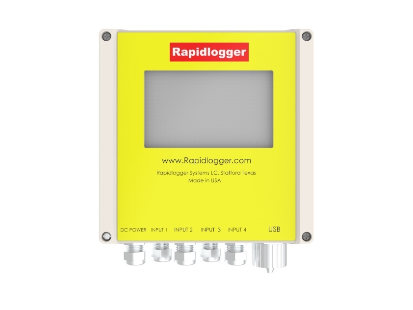

The Wiring Terminals of the Rapidlogger SE are shown below

Wire Terminal Layout – SE Unit
Installation of the Rapidlogger Max unit
The Rapidlogger Max unit is a larger Rapidlogger Unit that allows for the connection of a large number of analog and digital channels. The Rapidlogger Max unit mounting holes are shown below. In all applications the Rapidlogger Max lid should be kept tightly closed and the inside protected with a dry desiccant pouch. Use the following mounting dimensions.

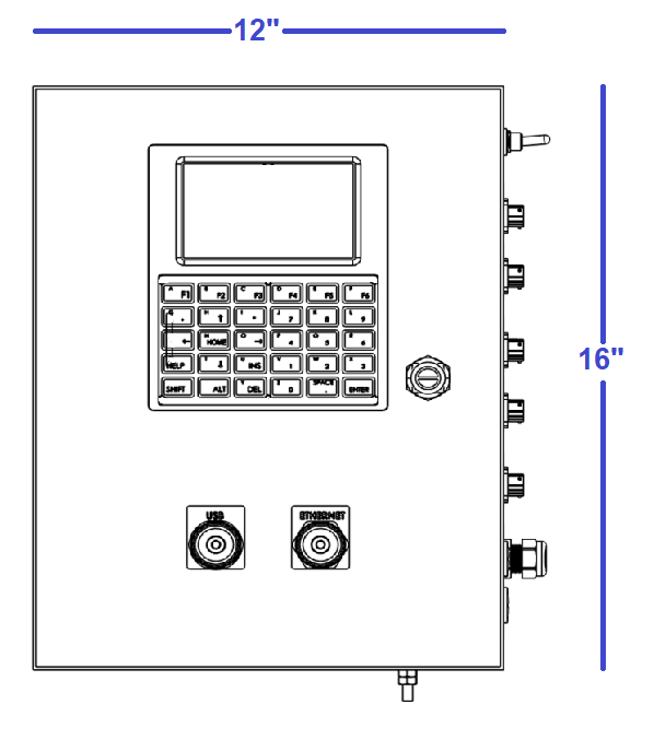
The Wiring Terminals of the Rapidlogger Max are shown below

Wire Terminal Layout – Max Unit
Installation of the Hazardous Area Barrier box
The hazardous area barrier box (if included) needs to be permanently mounted on a vertical surface. The box can be mounted in either orientation (long side vertical or short side vertical). For electrical details of the mounting refer to the installation drawing included in the Appendix A and the latest applicable edition of EN 60079-14 standard.
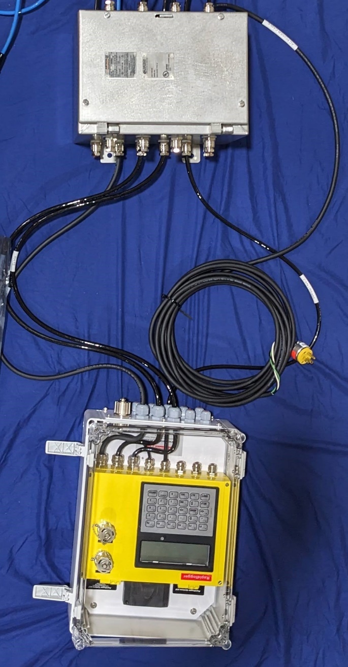
ATEX Barrier Box Location and Arrangement
The fuse sizes and must be followed. The Rapidlogger ATEX system utilizes a 1 ampere fuse. Do not substitute with a larger value. In case the fuse blows repeatedly, the source of the problem needs to be found and corrected instead of simply utilizing a larger fuse.
Power is supplied to the barrier box (12V DC, 24VDC, or 110/240VAC depending on the type of unit purchase) only via a cable suitable for Zone 1 or Zone 2 area, depending on the location of the unit. Cables for the standard intrinsically safe sensors come pre-terminated inside the barrier box. In case explosion proof sensors such as densitometers or turbine flowmeters, the cables need to be armored or suitable for the Zone 1 or Zone 2 area where they are routed.
The cement pumping pressure is measured by means of a pressure transducer interfaced to one of the system's four high resolution analog inputs. All four analog inputs support 4-20mA signal inputs and both 2 and 3 wire sensors. Based on factory standard programming the pressure transducer is interfaced to the first analog input on the system (mA1). All sensors are wired in to the terminal block JB1. For a 2 wire 4-20mA sensor the mA+ wire from the sensor should be connected to JB1-3 and the mA- signal wire from the transducer is connected to JB1-12.
All of the manufacturer installation instructions for the pressure transducer should be followed in order to retain the ATEX certification.

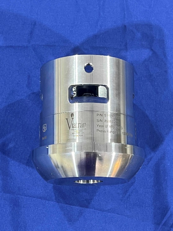
Many modern cement units are equipped with a Coriolis type densitometer (Micro Motion, Endress+Hauser, etc.). These densitometers can measure the flow-rate, volume, and density of the treatment fluid. The output from the densitometers is generally in the form of an analog output for density and a frequency output for the treatment rate and volume. These signals can be interfaced to the Rapidlogger unit and the data can be displayed and recorded.
The Micro Motion densitometer outputs density on its first 4-20mA output. Based on factory standard programming the density is interfaced to the second analog input (mA2) of the Rapidlogger. Both the analogs signals and the frequency signals from the Micromotion densitometer are electrically isolated. This means that the ground wire is not common between them. The mA+ wire from the densitometer transmitter should be connected to JB1-4 (24VDC +) and the mA- signal wire from the transmitter to JB1-13 (millampere input 2).

The Micro Motion densitometer outputs flow rate on one of its frequency output channels. This output is read into the Rapidlogger using one of its frequency inputs. The total volume is calculated and displayed by the Rapidlogger based on the total number of frequency pulses on this same channel. Based on factory standard programming the flow rate from the densitometer is interfaced to the first quadrature input (QA1). The FO+ (Frequency Output +) wire from the densitometer transmitter should be wired to JB1-16 and the FO- (Frequency Output -) wire to one of the available DC ground outputs such as JB1-7.
All of the manufacturer installation instructions for the densitometers should be followed in order to retain the ATEX certification.
Pump stroke sensors are proximity switches that sense the rotation of some rotating part of a pump. Both 2 and 3 wire type proximity switches (14) ranging from 12-24V can be interfaced to the Rapidlogger. Based on factory standard programming the pump stroke counter 1 is interfaced to the first frequency input (F1) of the Rapidlogger. It is generally not recommended to use Mag pickups with the Rapidlogger since the weak signal from them can cause loss of pulses over long cable runs.
1414

The frequency output wire from the proximity switch should be wired into to JB1-20. The output from the second pump stroke counter should be wired to (F2) JB1-21.
All of the manufacturer installation instructions for the inductive proximity sensor should be followed in order to retain the ATEX certification.
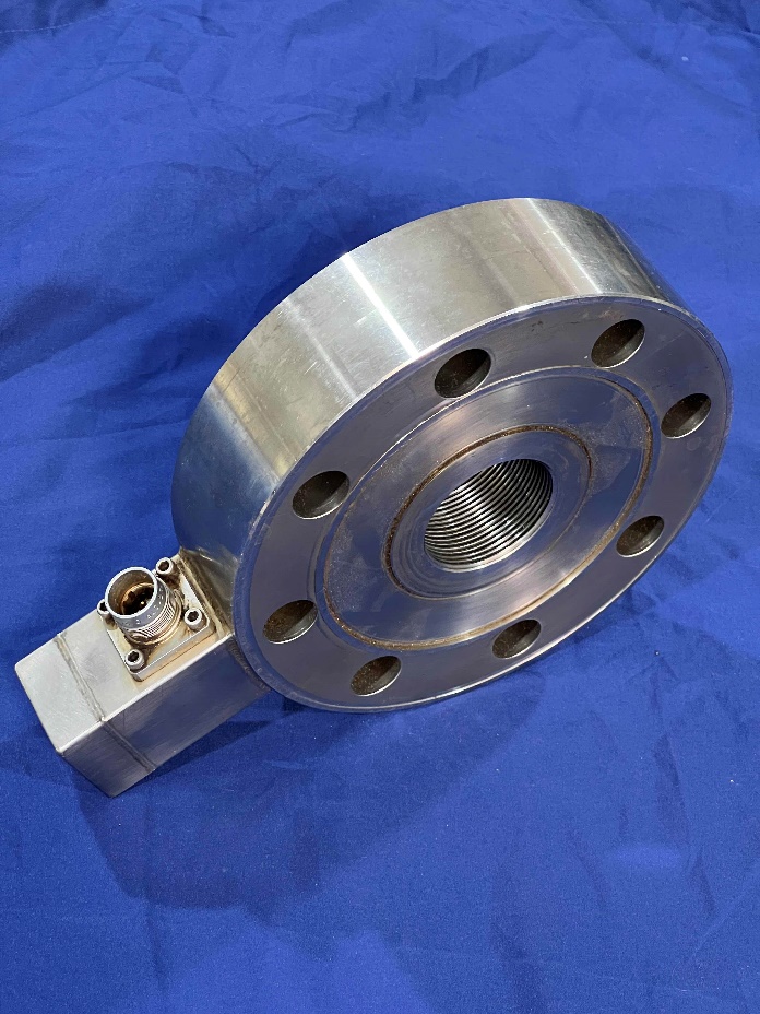
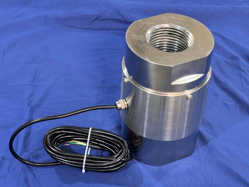
Tension and compression on slickline, wireline and coiled tubing units are measured by means of load cells. 4-20 milli ampere type load cells can be used with the Rapidlogger system. It is possible to use compression, tension, or bi-directional load cells with the Rapidlogger. Based on factory standard programming the load cell is interfaced to the first analog input on the system (mA1). All sensors are wired in to the terminal block JB1. For a 2 wire 4-20mA load cell the mA+ wire should be connected to JB1-3 (24VDC +) and the mA- signal wire to JB1-12 (milliampere input 1). The second load cell or pressure transducer can then be connected to the second milli ampere input on the system and so on.
For a 3 wire 4-20mA load cell the 12/24 V power wire should be connected to JB1-3 (24VDC +) the GND wire should be connected to JB1-9 (DC GND) and the mA signal wire should be connected to JB1-12 (milliampere input 1).
All of the manufacturer installation instructions for the load cell should be followed in order to retain the ATEX certification.
Tank level sensors are often used with the Rapidlogger System for instrumenting tanks, tubs, and pits in oilfield application. These can be used to measure cement slurry, water, and mud levels. Some tank level sensors work on the radar wave reflection principle, while others work on ultrasonic echo principle.
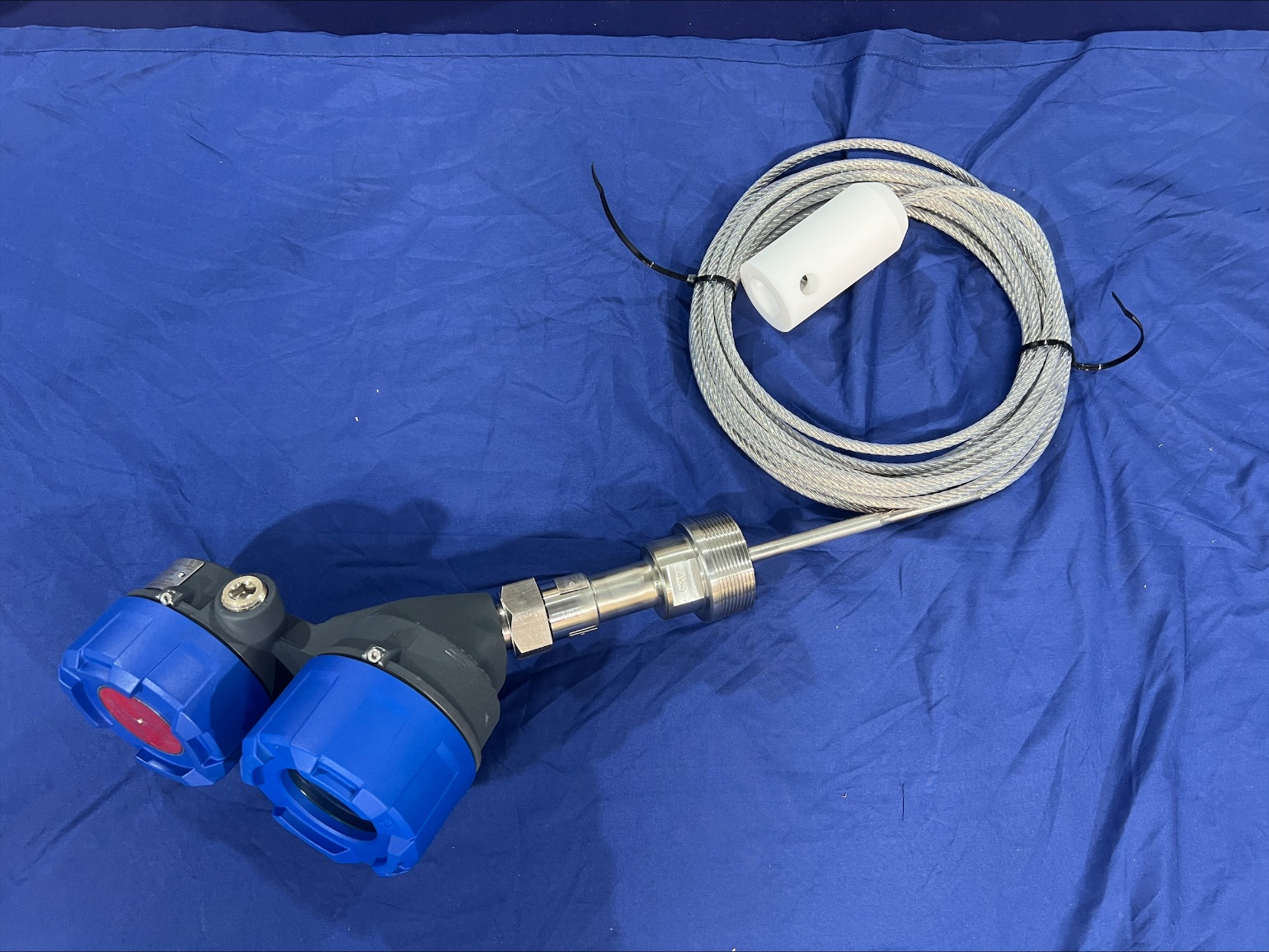
Most level sensors have a two wire 4-20mA output and can be directly interfaced to one of the Rapidlogger Analog inputs. The sensor’s power terminal should be connected to one of the (+24V) sensor power terminals on the Rapidlogger while the sensor’s signal terminal should be connected to one of the mA / analog inputs. The calibration of the level can be done using the Realtime Analog calibration function in the Rapidlogger System Utility.

Empty out the tank and use the utility to set the low desired output value. Then fill up the tank and set the high desired output value and Write Settings.
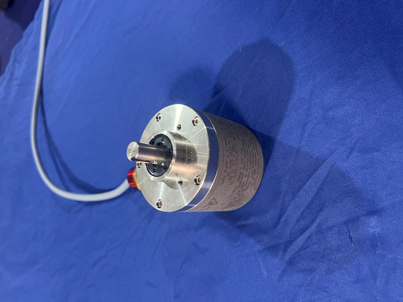
The Depth Encoder is used to measure the length or depth of wire or pipe in a hole for slickline, electric line, and coiled tubing operations. The wire/pipe is run on a friction wheel, which is connected to the shaft of the depth encoder, allowing the Depth Encoder to gather data.
The output of the Depth Encoder is a set of A and B pulse signals which are 90-degrees out of phase from each other. These pulses can either be 5V or 12V levels.
The Rapidlogger can be interfaced with up to two encoders and pulses ranging from 5V to 24V.
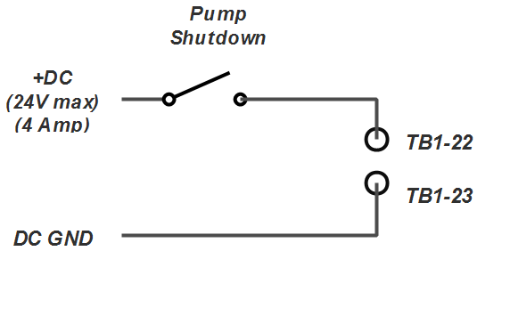
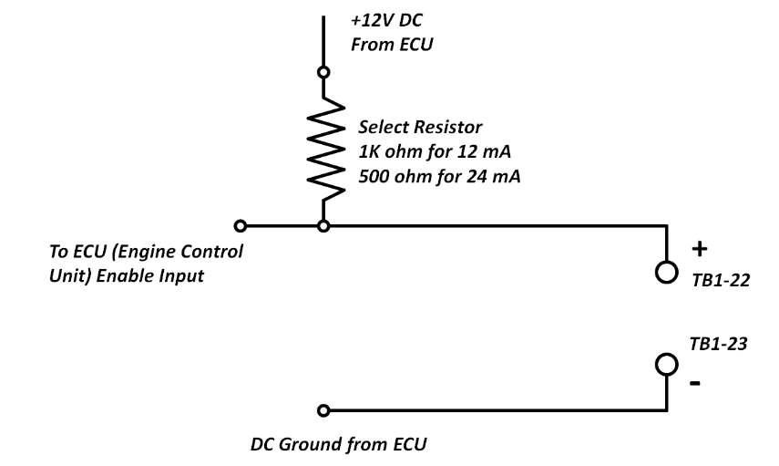
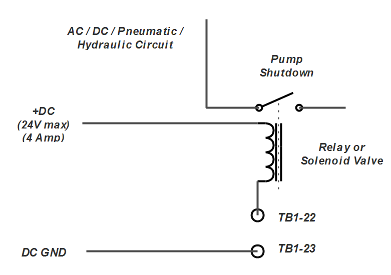
The Rapidlogger System can be used to actuate relays and valve solenoids in order to shut down a pumping unit when a dangerous condition is detected. This can include over pressure and over speed situations.
If the shutdown system on the pump is operated with DC Normally Open Contact then it can be wired as follows
For a shutdown system connected to an Engine control Unit with an Enable Input the shutdown can be wired as follows.
Other shutdown systems can be wired by means of an electrical relay or solenoid valve wired as follows.
Before powering up the system an inspection in accordance with EN 60079-17 latest applicable edition should be conducted. Notably it needs to be verified that all the cables glands and connectors are properly installed and sealed. No special adjustments are needed before startup. Once the safety inspection in accordance with EN 60079-17 is complete the unit can be powered up with the power switch.
The first power up must not be conducted in the presence of any hazardous atmospheres. In case a fuse blows immediately power down the system and locate the source of the fault before replacing the fuse and attempting to power up again.
« Previous · Contents · Next »