

Tech Note 107
This tech note describes the process to install, wire and set up an inductive proximity sensor to measure engine RPM on a Rapidlogger System, and how to verify the reading against the engine's own tachometer.
Sensor and Signal
The Rapidlogger engine RPM sensor is a Turck 4-pin inductive proximity switch (Rapidlogger part RLC-ProxSwitch, 00-91928) with an M12 connector. It is the same type of sensor that is used as a pump stroke counter. The sensor detects the steel teeth of the flywheel ring gear (or of the engine's speed sensing tone wheel) as they pass its face and produces one 24 VDC pulse per tooth. The Rapidlogger counts these pulses on one of its frequency inputs and converts the pulse rate to RPM.
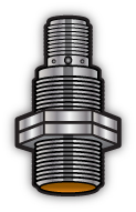
Figure 1: Inductive proximity sensor
The number of pulses per engine revolution is fixed by the engine and is equal to the number of teeth that pass the sensor. Engines on cementing, acidizing and fracturing units run between 360 and 4000 rpm. The pulse frequency seen by the Rapidlogger is:
Pulse Frequency (Hz) = Teeth x RPM / 60
Example: a 142 tooth ring gear at 2100 rpm produces 142 x 2100 / 60 = 4970 Hz.
The Rapidlogger frequency inputs read pulse rates up to 40 kHz. The inductive sensor is the limiting item: it switches reliably up to 5 kHz. Before installing, check the pulse frequency at the engine's maximum speed with the formula above.
WARNING: If Teeth x Maximum RPM / 60 is greater than 5000 Hz the inductive sensor cannot follow the teeth and the RPM reading will drop out or read low at high engine speed. In that case sense a slower target (for example a tone wheel or pulley with fewer teeth) or contact Rapidlogger support for a faster sensor.
Installing the Sensor
The sensor is normally installed in the engine's existing tachometer or speed sensor boss on the flywheel housing. Most diesel engines have a spare threaded boss beside the OEM magnetic pickup, or a timing hole cover that can be replaced by a drilled and tapped plate. The boss must point squarely at the tips of the ring gear teeth.
- Stop the engine and make sure it cannot be started while you work on the flywheel housing.
- Remove the plug or cover from the speed sensor boss. Confirm that the ring gear teeth are visible through the hole and are clean.
- Count the teeth on the ring gear, or read the tooth count from the engine data sheet. Write the number on the sensor cable tag; it is needed for the multiplier. To count, mark one tooth with paint and bar the engine over one full turn.
- Thread the sensor in until its face just touches the tip of a tooth, then back it out so that the gap between the sensor face and the tooth tips is 2 to 4 mm (0.080 to 0.160 in). Tighten the lock nut while holding the sensor so that it does not turn.
- Bar the engine over one full turn by hand and confirm that the sensor face does not touch the gear anywhere around the circumference.
- Route the sensor cable away from the exhaust, belts and fan. Secure it with tie wraps and leave a small service loop at the sensor.
NOTE: The sensing range of the sensor is 2 to 4 mm. Keep the gap within this range. A gap larger than 4 mm will give a zero or erratic reading, and the sensor face must never touch the gear.
Wiring the Sensor to the Rapidlogger
The sensor connects to the Rapidlogger with the detachable proximity sensor cable (Rapidlogger part 00-92169, 100 ft). The cable has an M12 socket at the sensor end and an Amphenol plug (PT01A-10-6P) at the Rapidlogger end. Plug the M12 end on to the sensor and the Amphenol end into the bulkhead connector on the Rapidlogger box that is labelled for the engine RPM input. No field wiring is required; the pinout is given below for reference and for making up extension cables.
| Function | Sensor M12 pin | Cable conductor | Amphenol pin | Rapidlogger terminal |
|---|---|---|---|---|
| +24 VDC sensor power | 1 (brown) | Red | B | JB1-4 (24 VDC OUT) |
| Not used | 2 (white) | White | F | Not connected |
| 0 V / ground | 3 (blue) | Black | A | JB1-10 (GND DC OUT) |
| Signal (pulses) | 4 (black) | Green | E | Frequency input assigned to engine RPM, F3 (J5-3) or F4 (J5-4) |
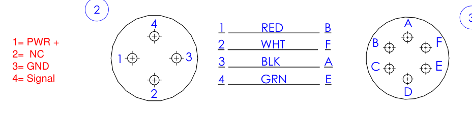
Figure 2: Proximity sensor cable 00-92169 pinout (M12 sensor end on the left, Amphenol unit end on the right)
NOTE: On a standard two pump unit the pump stroke sensors use frequency inputs F1 and F2 and the engine RPM cables are wired at the factory to F3 and F4 (main board terminals J5-3 and J5-4). A single engine option is wired to JB1-19 (F8). The wiring sheet supplied with your unit shows which frequency input each bulkhead connector goes to. The Input Number in the variable setup below must match.
WARNING: Do not connect the engine's own magnetic pickup or the ECU tachometer output to the Rapidlogger frequency input. A two wire magnetic pickup gives a sine wave that the Rapidlogger does not accept (see Tech Note 35). Use the Rapidlogger inductive sensor and cable.
Calculating the Multiplier
The multiplier converts the pulse frequency in Hz into RPM. There are 60 seconds in a minute and one pulse per tooth, therefore:
Multiplier = 60 / Teeth
The Offset is always 0 for a frequency variable.
| Pulses per revolution | Multiplier |
|---|---|
| 1 (single target on a pulley) | 60 |
| 110 teeth | 0.54545 |
| 126 teeth | 0.47619 |
| 142 teeth | 0.42254 |
| 160 teeth | 0.37500 |
Example: a 142 tooth ring gear gives a multiplier of 60 / 142 = 0.42254. Enter 0.42254 in the Multiplier field in the Rapidlogger System Utility.
NOTE: If the tooth count cannot be determined, enter 60 as a starting multiplier and correct it with the tachometer check in the last section of this tech note.
Setting up the Engine RPM Variable in the Rapidlogger System Utility
- Connect the PC to the Rapidlogger System over Ethernet or WiFi. Refer to Tech Note 9 for network setup.
- Open the Rapidlogger System Utility (version 4.81 or newer is available from the Rapidlogger website) and click 'Find Rapidlogger' to verify communication.
- Click 'Read All from Unit' to load the current variable configuration from the Rapidlogger.
- Click 'Write Vars File' to save a backup of the current setup on the PC before making changes (see Tech Note 13).
- Select the next unused variable number. On a standard two pump cementing setup variables 1 to 9 are in use and the engine RPM variables are 11 and 12.
- Set the following fields for the engine RPM variable:
| Field | Setting |
|---|---|
| Variable Name | EngineRPM1 |
| Variable Units | rpm |
| Decimal Places | 0 |
| I/O Type | Frequency |
| Input Number | 3 (the frequency input the engine RPM cable is wired to) |
| Multiplier | 60 / Teeth (0.42254 for 142 teeth) |
| Offset | 0 |
| Enable | Checked |
| Display | Checked if the RPM is to be shown on the LCD (maximum of 6 displayed variables) |
| Record/Transmit | Checked |
- Click 'Write One to Unit' and confirm that the message window shows 'Variable Apply OK'.
- For a second engine repeat the steps with variable 12, name EngineRPM2 and Input Number 4.
- Power cycle the Rapidlogger so that the new variables take effect.
Checking the Raw Signal
Start the engine and let it idle. On the Rapidlogger keypad press F6, F6, F5, F2 to open the frequency diagnostics screen. The frequency input that the engine sensor is wired to should show a steady reading in Hz equal to Teeth x RPM / 60. For a 142 tooth gear at 700 rpm idle this is 1657 Hz.
- Reading is 0: check the sensor gap, the cable connections at both ends and that the sensor cable is plugged into the connector for the input number used in the variable setup.
- Reading jumps around: the gap is too large, or the sensor is seeing bolt heads or casting instead of the gear teeth.
- Reading is steady at idle but falls at high speed: the pulse frequency is above the sensor switching frequency (see the first section).
Verifying Against the Engine Tachometer
Most engines have an RPM display on the engine control panel or the unit dashboard. Use it, together with a handheld tachometer, to confirm the Rapidlogger reading.
- Run the engine at a steady idle. Read the EngineRPM value on the Rapidlogger LCD or in RapidVu and compare it with the engine's own RPM display.
- Check the same speed with a handheld tachometer: an optical tachometer with a piece of reflective tape on the crankshaft damper or pulley, or a contact tachometer on the pulley nut.
- Repeat the comparison at a higher steady speed, for example the rated speed of 1800 or 2100 rpm.
- The Rapidlogger reading should agree with the handheld tachometer within a few rpm at both speeds. If the two agree the setup is complete.
- If the Rapidlogger reads high or low by the same ratio at both speeds the tooth count was wrong. Correct the multiplier as follows and write it to the unit:
New Multiplier = Old Multiplier x Reference RPM / Rapidlogger RPM
Example: with a multiplier of 0.42254 the Rapidlogger shows 1621 rpm while the handheld tachometer shows 1800 rpm. New Multiplier = 0.42254 x 1800 / 1621 = 0.46920. This corresponds to 60 / 0.46920 = 128 teeth. Enter the new multiplier, click 'Write One to Unit', power cycle the Rapidlogger and repeat the check.
NOTE: If the engine's own display and the handheld tachometer disagree, use the handheld tachometer as the reference. Engine panel displays can themselves be in error by a few percent.
The engine RPM sensor installation and setup is now complete. The EngineRPM variable is recorded in the job file and is available in RapidVu for display and in job reports.