

Tech Note 109
This tech note describes how to run an automatic density controlled cement mix with the RapidDCC program, once the RapidDCC valves and sensors have been installed and calibrated and the system tests in the RapidDCC User Manual have been passed. Installation, calibration and the system tests are covered in the RapidDCC User Manual, which is on the Rapidlogger flash drive.
What RapidDCC Does
RapidDCC mixes cement slurry to a set density without the operator working the water and bulk controls. It reads the slurry density from the Coriolis densitometer in the recirculating line, the water going in from the turbine water flow meter, the tank level from the radar level sensor and the bulk knife gate position from the linear position sensor. From these it drives the water control valve and the hydraulic solenoid valve on the knife gate to reach and hold the density and the tank level that the operator has entered.
The main screen shows the water control valve position in percent, the water flow rate in bpm, the tank level in percent, the actual density in ppg and the knife gate position in percent, together with the positions the program is currently commanding for the two valves. A Messages tab at the bottom right lists status and error messages with the time.

Figure 1: RapidDCC main screen: 1 water control valve, 2 water flow rate, 3 tank level, 4 actual density, 5 knife gate position, 6 commanded knife gate, 7 commanded water valve
Software and Licence
RapidDCC runs on a Windows PC and connects over the network directly to the Rapidlogger unit. RapidVu (version 4.4.41 or later) should be installed on the same PC and running to record the job; RapidVu needs no special setup for RapidDCC. The current program is RapidDCC 2.98.11.
RapidDCC is licensed to the serial number of the Rapidlogger unit. To obtain the program, send the unit serial number (Tech Note 2) to support@rapidlogger.com. Rapidlogger returns an installer built for that PC and that Rapidlogger; run it on the PC that will be used on the job. A new PC, or a replacement main board (which changes the serial number, Tech Note 106), needs a new installer from Rapidlogger.
Before the Job
- Power on the Rapidlogger and the RapidDCC junction box, and connect the PC to the unit by Ethernet or WiFi (Tech Note 9). Ping the unit, normally 192.168.0.5.
- Leave the bulk and water switches on the panel off until the program is running in Automatic mode.
- Turn on the hydraulic power pack so that the knife gate can move, and the water pump so that water can flow when the valve opens.
- Check that the level sensor rod and splash guard are clean. With the tank empty the level should read 0 to 5 percent.
- Start RapidVu and confirm that it is receiving data from the unit.
Starting RapidDCC
- Start RapidDCC. Enter the Well name and the Job name; both are required before the program will connect. Tick 'Suggest a Job Name' to have a name generated.
- Check that the IP address shown next to the Connect button is the address of the Rapidlogger. Change it from the File menu, TCP/IP, if needed.
- Click Connect. On success the small picture of the Rapidlogger at the top left starts flashing, the button turns green and reads Disconnect, and the message area shows 'Connected to Rapidlogger' with the unit's firmware and FPGA versions. The sensor readings fill in. A red button means the connection failed: check the ping, the IP address and the Windows firewall.
- Click Recipe. Enter the Desired Density (ppg), Yield and Mix Fluid for the Lead slurry, and for the Tail slurry if there is one. Click 'Choose Lead Slurry' to make the lead recipe the target. The chosen recipe is shown on the main screen under the GO button.

Figure 2: Job Information box at start-up. Well name and Job name are required

Figure 3: Connected: green Disconnect button, firmware and FPGA versions in the message area, sensor readings filled in
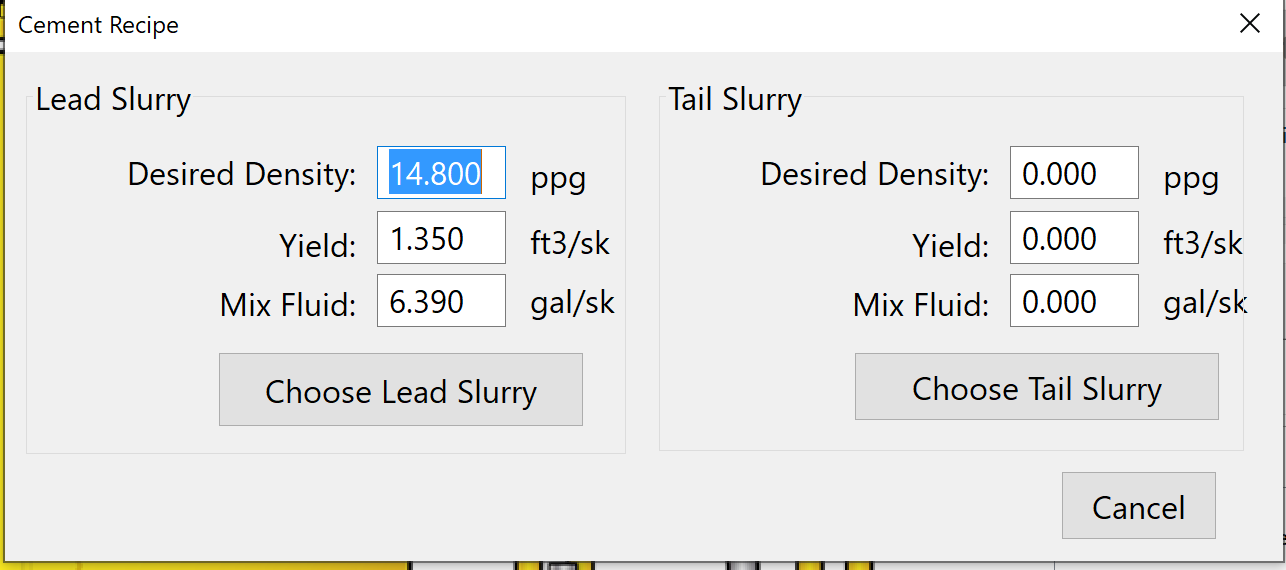
Figure 4: Cement Recipe screen with the lead slurry entered
The program keeps a log of every job in the folder below, by well and job name. A finished job can be replayed from the File menu, Playback.
C:\Users\<user name>\AppData\Roaming\RapidDCC\Logs\<Well>\<Job>
The Three Modes
| Mode | What it does | When to use it |
|---|---|---|
| Manual | The program only displays the readings. The operator moves the knife gate with the lever; the water valve is held at 75 percent open. | After connecting, and whenever the crew wants to run the mix by hand |
| Test | The operator sets the water valve and knife gate positions in percent with the sliders or boxes and presses Set Valve. The valves move to those positions and stay there. | Checking the valves after installation or repair, or running a job with the valves driven from the PC but not automatically |
| Automatic | The operator enters a tank level set point and presses GO. The program drives both valves to reach and hold the recipe density and the level. | Normal mixing |
Switch between modes with the Manual, Test and Automatic buttons at the top of the screen. In Test mode the water valve takes about 20 seconds to travel from closed to open and the knife gate about 15 seconds. The status LED for a valve is yellow while it is moving and green when it has reached the set position.
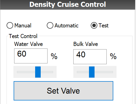
Figure 5: Test mode: water valve 60 percent and bulk valve 40 percent entered, Set Valve sends them
Running Automatic Density Control
- Make sure the bulk and water switches on the panel are off.
- Choose the target recipe with the Recipe button.
- Enter the target tank level in the box or with the slider above the GO button. 65 percent is recommended.
- Select Automatic mode and press GO.
- Turn on the bulk and water switches on the panel so that the valves can take effect.
- Watch the stages described below. When the tank level has reached the set point, start pumping the slurry out. The program keeps adding water and bulk to hold the density and the level while the tank is drawn down, and continues to hold the density when the mixing tank overflows the weir into the averaging tank.
- To change the level set point, press Pause, enter the new value and press GO again. To change to the tail slurry, click Recipe and 'Choose Tail Slurry'; the target under the GO button changes.
- At the end of the job press Pause, switch to Manual mode, turn off the panel switches and click Disconnect.
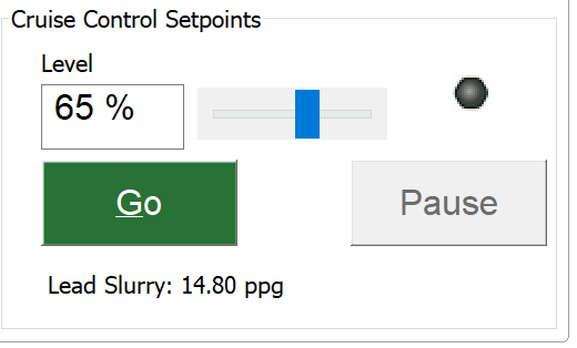
Figure 6: Level set point 65 percent, GO button, chosen recipe shown below it
What happens after GO
- Reach Minimum Water: the knife gate stays closed while 2 barrels of water go into the tank. The water added so far is shown in the Min Water (bbl) box. No bulk can be added in this stage.
- Reach Initial Density: the water valve drops to 10 percent and the knife gate opens gradually until the actual density is within 2 ppg of the target.
- Reach and Maintain Target: both valves are controlled together to reach the density and the level set points and then hold them until the set points are changed or the program is paused.

Figure 7: Reach Minimum Water stage: State box reads Reach Min, knife gate closed, water going in
NOTE: If the tank level is above the high water mark (95 percent unless changed) the program opens neither valve, because adding anything would overflow the tank. Draw the tank down to within about 5 percent of the level set point and both valves start. If the slurry in the tank is heavier than the recipe when GO is pressed, the program adds water only until the density comes down to the target, then opens the gate.
Status LEDs and Messages
Five status LEDs on the main screen show the state of the control at a glance. All grey means the cruise control is off or not running. In general yellow means working toward the set point, green means the set point is reached, and red means the set point has not been reached in the expected time but the program is still trying.
| LED | Green | Red |
|---|---|---|
| Density | Density set point reached | Not reached within 15 to 20 seconds; the program keeps trying |
| Knife Gate | Gate at the commanded position | Position sensor not at the commanded position |
| Water Flow Meter | Water flow about as expected for the valve position | Water flow not as expected |
| Water Control Valve | Valve at the set point | Set point not reached within 15 to 20 seconds |

Figure 8: Automatic mode holding the set points: density LED green, valve LEDs green, Water Cmd and Bulk Cmd boxes blue
Two faults are also shown by a box blinking red on the screen:
- Bulk Cmd % blinking red: the knife gate has not moved to the commanded position within 20 seconds. The message reads 'no movement detected on the hydraulic cylinder / knife gate'. Check that the hydraulic power pack is on and that the position sensor is plugged in.
- Water flow box blinking red: the water valve is more than 10 percent open but no flow is measured. The message reads 'Water flow not detected'. Check that the water pump is on and the water flow meter is working.
- 'Water valve not operational. Please verify that the power is connected': the valve feedback has not followed the command within 15 seconds. Check the power switch on the junction box and the valve cable.

Figure 9: Bulk Cmd % box red: the knife gate has not reached the commanded 22 percent
After the Job
- Wash the level sensor rod, bracket and splash guard before the cement sets. A cement plug on the rod gives a false level on the next job and the program will then control the tank level wrongly.
- The job data is in the RapidVu job file and report (Tech Note 19), and the RapidDCC log in the folder above can be replayed from the File menu.
For further help contact support@rapidlogger.com with the unit serial number, the RapidDCC version, a screenshot of the main screen and the text of the messages in the Messages tab.