

Tech Note 108
This tech note describes how to use the RapidVQI program to mix cement or another slurry to a target volumetric ratio without a densitometer, once the RapidVQI sensors have been installed and calibrated. Installation and calibration of the sensors are covered in the RapidVQI User Manual, which is on the Rapidlogger flash drive.
What RapidVQI Does
RapidVQI measures the quality of a mix without a densitometer. A turbine flow meter counts the water (or brine or acid) going into the mixing tank and a guided wave radar sensor measures the tank level. Any rise in the tank level beyond the metered water is taken to be dry or liquid additive, and any fall in the level is slurry pumped out through the slurry flow meter. From these the program keeps a running ratio of additive to total mix, called the volumetric quality.
The volumetric quality is a number between 0 and 1 with no units. A value of 0 is pure water. A value of 0.3 means that every gallon of slurry holds 0.7 gallon of water and 0.3 gallon of additive such as cement. The number updates on the screen in real time while the mix is made and pumped.
What Must Be in Place
RapidVQI runs on a Windows PC and connects over the network directly to the Rapidlogger unit. RapidVu is not needed for the calculation but is normally run on the same PC to record and graph the job. The current program is RapidVQI 2.0.14, supplied on the Rapidlogger flash drive and from rapidlogger.com (Support, Downloads).
The three sensors below must be installed and calibrated as described in the RapidVQI User Manual before the program is used. On a unit ordered with RapidVQI the variables are set up at the factory; click 'Read All from Unit' in the Rapidlogger System Utility to confirm they are present.
| Sensor | Rapidlogger terminal | Variable | Units |
|---|---|---|---|
| Water flow meter (turbine, in the water inlet line) | QA2, 24 VDC out, GND | WaterFlow | bpm |
| Slurry flow meter (Coriolis, in the slurry outlet line) | QA1 and mA3, GND | SlurryFlow | bpm |
| Tank level sensor (guided wave radar, 4-20 mA) | Analog input 4 | LevelSensor | ft |
| Result written back by RapidVQI (no sensor) | none | ActualSlurry | ratio |
NOTE: The ActualSlurry variable is a CalculatedScaled variable with no input. RapidVQI writes the volumetric quality into it so that the value appears on the LCD, in the RapidVu job file and on the job report. Do not delete it.
Before the Job
- Power on the Rapidlogger and connect the PC to it by Ethernet or WiFi (Tech Note 9). Ping the unit, normally 192.168.0.5, before starting RapidVQI.
- Start RapidVu if the job is to be recorded. RapidVu and RapidVQI can run on the same PC or on two PCs on the same network.
- Check that the level sensor rod and its splash guard are clean. Cement left on the rod from the last job is the most common cause of a wrong level reading.
- With the tank empty, confirm on the RapidVQI screen (after connecting, below) that the level reads close to 0 ft. If it does not, wash the rod.
- Plan to run the water valve either at least half open or fully closed. The 2 inch turbine meter is not accurate below about 20 to 40 gpm (0.5 to 1 bpm), so a valve that is cracked open gives a wrong water total and a wrong volumetric quality.
Tank Setup
Start RapidVQI and press the Tank Setup button. Choose Straight Tank or Stepped Tank and enter the tank data. Press Save; the data is kept on the PC and loaded automatically the next time the program starts. Tank data cannot be changed while the program is connected or the VQI calculation is running.

Figure 1: RapidVQI main screen. Connect at top left, VQI controls and Tank Setup at the right
Straight tank
A tank whose cross section does not change much from bottom to top. Enter:
- Maximum Capacity: tank volume in US gallons at the maximum fluid level. One oilfield barrel is 42 US gallons.
- Tank Height: the fluid level in feet at that maximum volume.
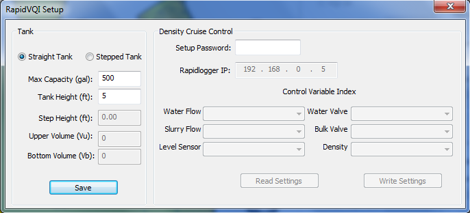
Figure 2: RapidVQI Setup screen with Straight Tank selected. The Rapidlogger IP address is also entered here
Stepped tank
A tank with a large change in cross section at some height, for example a narrow bottom section under a wide top section. Enter:
- Total Vol: tank volume in US gallons at the maximum level. It equals the upper and bottom part volumes added together.
- Upper Part Volume (VU): volume in US gallons of the part above the step.
- Bottom Part Volume (VB): volume in US gallons of the part below the step.
- Tank Height (h): the fluid level in feet at the maximum volume.
- Step Height (s): the height of the step in feet, measured from the tank floor as the level sensor sees it.

Figure 3: Stepped tank parameters: h, s, VU and VB
Connecting to the Rapidlogger
Check that the Rapidlogger IP address on the Setup screen is the address of the unit, normally 192.168.0.5. Open the Data menu, choose Connect and click Connect in the dialog box that appears. When the connection is made the small picture of the Rapidlogger at the top left of the screen starts flashing and the Connect button turns green and reads Disconnect. If the button turns red the connection failed: check that the unit answers a ping, that the PC and the unit are on the same network, and that the Windows firewall is not blocking the program.
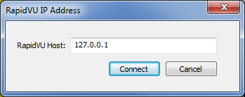
Figure 4: Connect dialog box
Running the Mix
- In the VQI section of the main screen select VQI On.
- Enter Desired Slurry: the volumetric ratio wanted for the mix, between 0 and 1. Enter 0.5 for a mix that is half water and half additive by volume.
- Enter Initial Slurry: the ratio of whatever is already in the tank. Enter 0 for an empty tank or a tank holding only water. Enter the known ratio if the program is being started in the middle of a mixing job.
- Press VQI Start. The VQI LED and the VQI Start button turn green while the calculation runs.
- Open the water valve (at least half way) and put water in the tank, then start the mixer and begin adding the bulk and liquid additives. Water and additive can be added at the same time; the program works out the proportions from the water meter and the level.
- Watch the volumetric quality rise toward the desired value. When it is close, begin pumping the slurry. The slurry flow meter tells the program how much has left the tank, so the ratio stays correct as more water and additive go in.
- Keep the water valve at least half open when water is needed and fully closed when it is not. Do not throttle it.
- For a stepped tank, let the first tank of slurry come close to full at the correct volumetric quality before pumping. The step makes the level-to-volume calculation less certain while the tank is only partly full.

Figure 5: RapidVQI running: Disconnect button green, VQI On, Desired Slurry 0.50 entered and the VQI LED green after VQI Start
NOTE: If the unit has RapidDCC density cruise control, leave VQI Off. RapidDCC controls the water and bulk valves from the densitometer and does not use the volumetric quality calculation.
After the Job
- Press VQI Stop, then Data, Disconnect, and close the program.
- Wash the level sensor rod, bracket and splash guard thoroughly before the cement sets. A cement plug on the rod stops the sensor reading correctly on the next job.
- The volumetric quality for the job is in the ActualSlurry column of the RapidVu job file and on the job report (Tech Note 19).
If Something Is Wrong
| Symptom | Likely cause | Action |
|---|---|---|
| Level not near 0 ft with the tank empty | Cement or mud on the radar rod | Wash the rod and bracket; see Tech Note 48 for the sensor itself |
| Connect button turns red | Network | Ping the unit; check the IP address in the connect dialog, the cable or WiFi (Tech Note 9) and the Windows firewall |
| Volumetric quality does not rise while additive is added | Level sensor not seeing the rise, or water meter reading high | Check that the level on the screen follows the tank; check the water flow reading against the valve position |
| Volumetric quality jumps around | Splash guard fitted backwards, or the rod in the mixing stream | Turn the splash guard so the rod is shielded from the flow rotation |
| Water flow reads zero with the valve open | Valve cracked open only, or wiring at QA2 | Open the valve at least half way; check the meter wiring and its multiplier (Tech Note 17) |
| WaterFlow, SlurryFlow or LevelSensor missing in the Utility | Variables not set up | Set them up per the RapidVQI User Manual section 4.4, or ask Rapidlogger for the unit's setup file with the serial number (Tech Note 2) |
For further help contact support@rapidlogger.com with the unit serial number, the RapidVQI version (Help menu) and a screenshot of the RapidVQI main screen.