

Tech Note 112
This tech note describes how to check and calibrate a pressure channel on a Rapidlogger, from the quick zero on the keypad to a full two-point calibration against a reference gauge or deadweight tester, and how to tell a transducer fault from a scaling error.
How the Pressure Channel Works
An oilfield pressure transducer is a strain-gauge diaphragm with a built-in amplifier that gives a 4-20 mA current (or sometimes a 0-5 V or 0-10 V signal) proportional to pressure: 4 mA at zero pressure and 20 mA at the full-scale pressure stamped on the transducer, for example 0-10,000 psi. The Rapidlogger powers the transducer from its 24 V DC OUT terminals and reads the signal on an analog input.
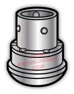
Figure 1: Wing-union type pressure transducer as fitted on a treating line
The unit converts the raw signal to a displayed pressure with two numbers stored in the variable, the Multiplier and the Offset (Tech Note 104):
Displayed pressure = (raw signal x Multiplier) + Offset
The factory sets the Multiplier for the transducer range supplied with the unit. A calibration adjusts these two numbers so that the displayed pressure matches a known reference.
Three Levels of Check
- Zero check (every job). With the line bled to atmosphere the display should read 0 psi, or close to it. A small offset of a few psi is normal and is removed from the keypad.
- Reference check (when in doubt, or after a transducer change). Compare the display against a calibrated reference gauge at one or two pressures. If it agrees within the accuracy you need, no change is required.
- Two-point calibration (when the reference check fails). Measure at zero and at a known high pressure, compute a new Multiplier and Offset, write them to the unit.
Zero From the Keypad
With the pressure line open to atmosphere press F6 and then F1 from the main screen (Figure 2) to open the pressure menu (Figure 3), then F1 to zero the pressure. F2 undoes the zero. If the true pressure is known but not zero, for example a static wellhead pressure read on a certified gauge, press F3 and enter the known value instead of zeroing.

Figure 2: Main screen in the cementing mode; F6 opens the System menu, then F1 Pressure

Figure 3: Pressure menu: F1 Zero, F2 Undo, F3 Enter a known value
The keypad zero is applied to the current job and is the right tool for the small drift seen from day to day. It is not a substitute for a calibration when the error grows with pressure.
Two-Point Calibration
You need a way to apply a known pressure to the transducer: a deadweight tester, a hand pump with a calibrated reference gauge, or a comparison against a certified gauge on the same line during a pressure test. The reference should be at least four times more accurate than the error you want to correct.
- Back up the Rapidlogger variables with the Rapidlogger Utility (Tech Note 13) so the original Multiplier and Offset can be restored (Tech Note 43).
- In the Utility, Ping the unit, Read All from Unit, and step to the pressure variable (on a cementing setup this is variable 1, Pressure, Figure 4). Note the current Multiplier and Offset.
- Bleed the line to atmosphere. Record the displayed pressure (point 1, actual 0 psi). Do not zero from the keypad during a calibration.
- Apply the high reference pressure, as close to the working pressure of the job as the equipment allows. Wait for the reading to settle. Record the displayed pressure and the reference pressure (point 2).
- Enter the original Multiplier, the two displayed values and the two actual values in the two-point calibration spreadsheet RapidloggerMultiplierCalculationTwoPointSensorCalibration.xlsx (available from support@rapidlogger.com). It returns the corrected Multiplier and Offset.
- Enter the new Multiplier and Offset for the variable in the Utility and press Write One to Unit.
- Power cycle the unit.
- Check again at zero and at the reference pressure, and at a mid-scale point if the reference allows. The display should now agree with the reference within the transducer's accuracy.
- Record the date, the transducer serial number, the reference used and the new Multiplier and Offset on the unit's calibration sheet.

Figure 4: Rapidlogger Utility showing variable 1, Pressure, with its Multiplier and Offset
Reading the Error
The pattern of the error tells you what is wrong:
- Reads a constant number of psi high or low at every pressure: offset error. The keypad zero or the Offset field corrects it.
- Error grows in proportion to pressure (for example 1 % low at every point): Multiplier error, usually because the variable is scaled for a different transducer range than the one fitted. A 5,000 psi transducer on a channel scaled for 10,000 psi reads half the true pressure. Check the range stamped on the transducer before touching the Multiplier.
- Reads zero or full scale and does not move: wiring or a failed transducer. Check the 24 V supply at the transducer, the loop current with a meter (4 to 20 mA), and the cable.
- Reads correctly but jumps or is noisy: loose connection, water in the connector, or a damaged cable. The Rapidlogger's filtering removes pump pulsation, not an intermittent wire.
- Reads correctly at zero but does not reach the expected pressure during a job: the transducer may be ranged too low and is saturating at 20 mA.
What Accuracy to Expect
An oilfield transducer is typically rated 0.25 % to 1 % of full scale. On a 10,000 psi transducer that is 25 to 100 psi anywhere in the range, so a reading of 50 psi on a bled line is not necessarily a fault. Choose the transducer range to suit the job: a 5,000 psi transducer on a 3,000 psi cement job gives a better record than a 15,000 psi frac transducer.
NOTE: Always keep a copy of the variables file from before the calibration. If the display is worse after the change, restore the file (Tech Note 43) and start again.
Related tech notes: #104 (how Multiplier and Offset work), #8 (making small adjustments with the Utility), #13 and #43 (backing up and restoring variables), #17 (calibrating pump total and rate), #57 (over-pressure shutdown). The pressure channel calibration is now complete.