

Tech Note 113
This tech note describes how to calculate the volume per pulse for a pump rate sensor, how that number becomes the Multiplier for the pump total and pump rate variables in the Rapidlogger, and how to confirm the result with a pumping test. It is the calculation behind the multipliers used in Tech Note 17.
What the Rapidlogger Counts
A pump rate sensor (stroke counter) is a proximity switch, magnetic pickup or Hall sensor that gives one pulse every time a bolt head, sprocket tooth or plunger collar passes in front of it (Figures 1 and 2). The Rapidlogger counts those pulses on a frequency input (Tech Note 103). The unit does not know what a pulse is worth; the Multiplier tells it:
Pump total multiplier = barrels per pulse
Pump rate multiplier = barrels per pulse x 60
The factor of 60 turns pulses per second into barrels per minute. So the whole setup comes down to one number: how many barrels the pump moves between two pulses.
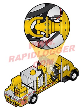
Figure 1: Proximity sensor facing the flange bolts on a cement pump truck
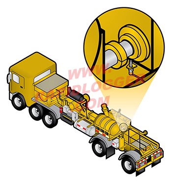
Figure 2: Proximity sensor on a fracturing pump plunger: one pulse per revolution
Step 1: Barrels per Pump Revolution
For a positive-displacement plunger pump every revolution of the crankshaft moves each plunger through one stroke. The volume per revolution is:
Volume per revolution (cubic inches) = 0.7854 x D x D x L x N
where D is the plunger diameter in inches, L is the stroke length in inches and N is the number of plungers (3 for a triplex, 5 for a quintuplex). One barrel is 9,702 cubic inches, so:
Barrels per revolution = 0.0000810 x D x D x L x N
For example, a triplex cement pump with 4.5 inch plungers and an 8 inch stroke gives 0.0000810 x 4.5 x 4.5 x 8 x 3 = 0.0394 barrels per revolution, about 1.65 US gallons.
Pump makers usually publish this number as displacement per revolution or gallons per stroke for each plunger size. Use their figure if you have it; the formula is for when you do not.
Step 2: Pulses per Pump Revolution
Now count how many pulses the sensor produces for one revolution of the crankshaft:
- Sensor facing bolt heads on a flange on the crankshaft or pinion: pulses per revolution = number of bolt heads (or teeth) in front of the sensor, multiplied by the gear ratio between that shaft and the crankshaft if the flange is not on the crankshaft itself. A flange with 8 bolts on a shaft turning 2.5 times per crankshaft revolution gives 20 pulses per revolution.
- Sensor on one plunger (fracturing pumps, Figure 2): one pulse per revolution.
- Sensor on a cam or a single target: one pulse per revolution.
If you are not sure, bar the pump over one full crankshaft revolution by hand and count the pulses on the Rapidlogger display, or on a meter at the sensor.
Step 3: Barrels per Pulse
Barrels per pulse = barrels per revolution / pulses per revolution
In the example, 0.0394 / 20 = 0.00197 barrels per pulse. This is the Multiplier for the pump total variable (Pump1Total). The Multiplier for the pump rate variable (Pump1Rate) is the same number times 60: 0.00197 x 60 = 0.118.
Step 4: Enter the Multipliers
- Back up the variables with the Rapidlogger Utility (Tech Note 13).
- Read All from Unit, step to Pump1Total, enter the barrels-per-pulse value in the Multiplier field (Figure 3), Write One to Unit.
- Step to Pump1Rate, enter the value times 60, Write One to Unit.
- Check that both variables use the same Input Number, so they count the same sensor (Tech Note 103).
- Power cycle the unit.

Figure 3: Rapidlogger Utility: the Multiplier field of the selected variable
Step 5: Confirm With a Pumping Test
The calculation gives the theoretical displacement. A real pump delivers a little less because of valve slip and air, typically 90 to 98 percent of theoretical on water, and the difference is what the pumping test in Tech Note 17 corrects: pump a known volume (10 barrels of water for a cement pump), compare the Pump1Total reading with the volume pumped, and let the spreadsheet scale the Multiplier to match. Both the total and the rate multiplier are corrected by the same factor.
The default cementing setup in Tech Note 17 uses 0.000215 barrels per pulse. That value suits the pump and sensor it was set up for and is only a starting point. Any pump with a different plunger size, stroke, sensor target or gear ratio needs its own number from the steps above, followed by the pumping test.
Common Mistakes
- Using gallons per stroke from the pump maker as if it were barrels: divide by 42.
- Counting bolt heads on a flange that turns faster or slower than the crankshaft and forgetting the gear ratio.
- Setting the total multiplier correctly but leaving the rate multiplier at the old value, so the rate and the total disagree.
- Double pumps: Pump2Total and Pump2Rate need their own values if the second pump has a different plunger size or sensor.
- Running the pump dry at the end of a pumping test, which makes the correction look worse than it is.
NOTE: After any change to the multipliers run the pumping test in Tech Note 17 before the next job and record the final values on the unit's calibration sheet.
Related tech notes: #17 (calibrating pump total and rate), #103 (frequency inputs and variable mapping), #11 (cementing variable settings), #104 (how Multiplier and Offset work), #35 (flowmeters as an alternative to stroke counters). The pump rate and total setup is now complete.